Disk recording and/or reproducing device

Inactive Publication Date: 2008-12-04
SONY CORP
View PDF4 Cites 6 Cited by
  • Summary
  • Abstract
  • Description
  • Claims
  • Application Information

AI Technical Summary

Benefits of technology

[0013]The inventors of the invention have recognized that in related art disk recording and / or reproducing devices, although a cover for preventing dust or the like from invading into a disk housing portion is provided, because the area of an outer periphery (or a circumference portion) of the cover, opposed to the main surface of the disk tray, is relatively small, the air current involved in disk rotation flows through a space between the outer periphery (or the circumference portion) of the cover and the main surface of the disk tray, thus resulting in causing a relatively high noise level due to the air current.
[0015]According to the disk recording and / or reproducing device of the embodiment of the invention, the dimension of the width of the annular contact portion in a direction orthogonal to the circumferential direction thereof is larger than the dimension of the thickness of the disk cover, and the annular contact portion is brought into contact with an entire periphery of the disk housing portion of the disk tray. Accordingly, the space between the disk cover and the disk tray can be eliminated or can be made small as much as possible, thereby preventing or suppressing the air current from flowing through the space and preventing the noise level due to the air current flowing through the space from increasing. As such, the noise level caused by rotation of the disk-like recording medium can be decreased.

Problems solved by technology

The inventors of the invention have recognized that in related art disk recording and / or reproducing devices, although a cover for preventing dust or the like from invading into a disk housing portion is provided, because the area of an outer periphery (or a circumference portion) of the cover, opposed to the main surface of the disk tray, is relatively small, the air current involved in disk rotation flows through a space between the outer periphery (or the circumference portion) of the cover and the main surface of the disk tray, thus resulting in causing a relatively high noise level due to the air current.

Method used


Image

  • Disk recording and/or reproducing device
  • Disk recording and/or reproducing device
  • Disk recording and/or reproducing device

Examples


Embodiment Construction

[0033]A disk recording and / or reproducing device in which invasion of dust or the like into a disk housing portion can be avoided and a noise level caused by rotation of a disk-like recording medium can be decreased was realized in a relatively simple construction by providing an annular contact portion to an outer periphery of a disk cover and by making the dimension of the width of the annular contact portion larger than the dimension of the thickness of the disk cover.

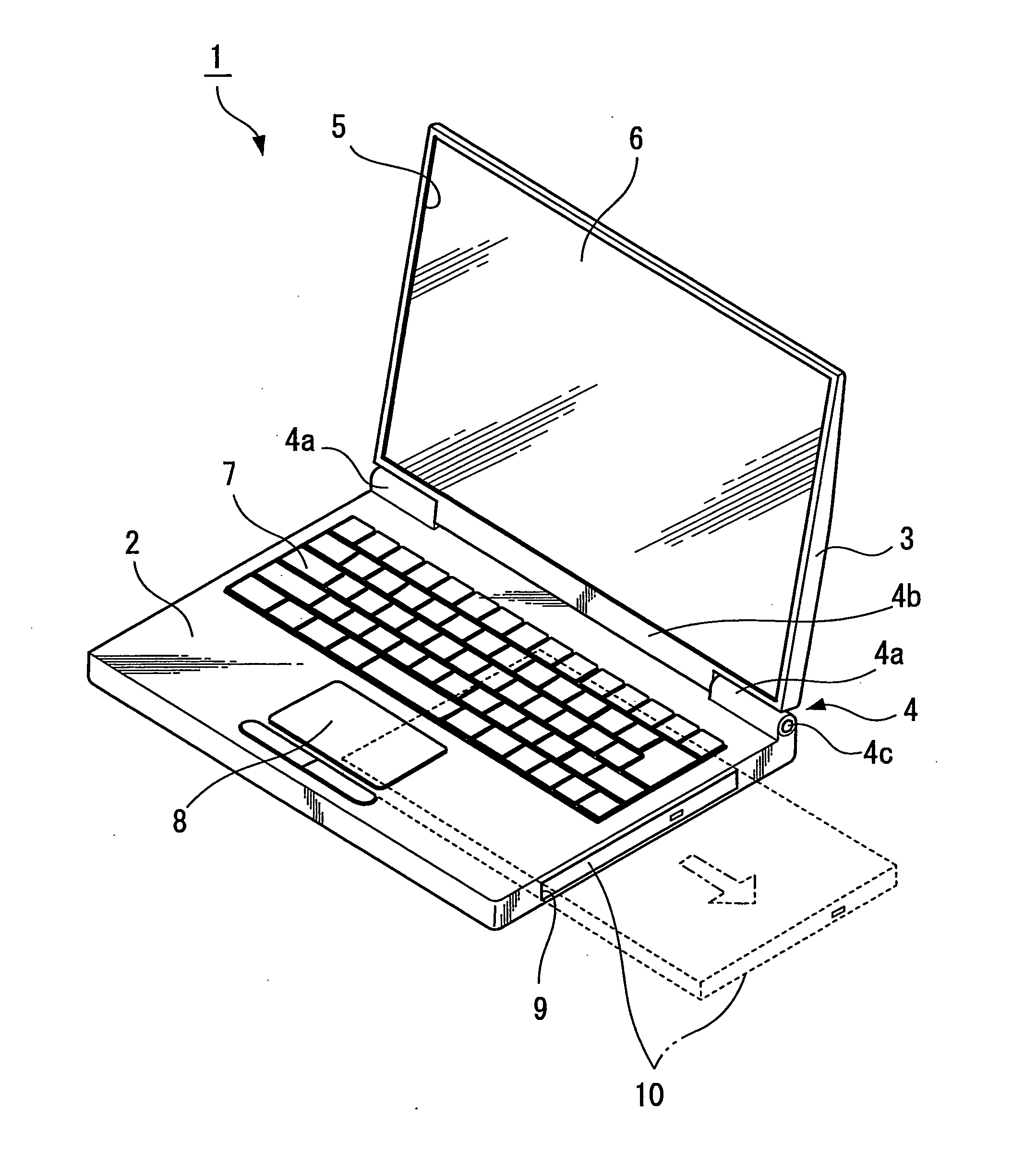
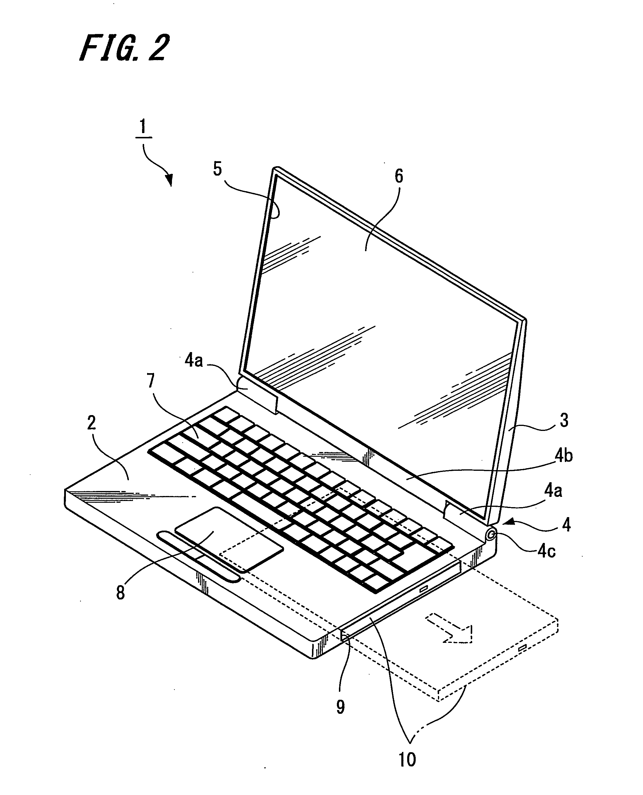
[0034]FIGS. 2 to 17 illustrate an example of an embodiment of the invention. That is, FIGS. 2 to 17 illustrate an example of a disk recording and / or reproducing device according to the embodiment of the invention. FIG. 2 is a perspective view of a laptop personal computer as an example of the disk recording and / or reproducing device according to the embodiment of the invention; FIG. 3 is a perspective view illustrating an appearance of a disk drive device of the laptop personal computer; FIG. 4 is a perspective view...


PUM


Abstract

A disk recording and / or reproducing device includes a disk tray having a concave disk housing portion for putting in and taking out a disk-like recording medium; a tray housing case supporting the disk tray so as to be movable in a direction in which the disk tray is inserted and ejected; and a disk cover mounted to the tray housing case and covering over the disk housing portion of the disk tray when the disk tray is housed in the tray housing case. The disk cover includes an annular contact portion at an outer periphery thereof, extending outwardly and continuous in a circumferential direction thereof, a dimension of a width of the annular contact portion is larger than that of a thickness of the disk cover, and the annular contact portion is brought into contact with an entire periphery of the disk housing portion of the disk tray.

Description

CROSS REFERENCES TO RELATED APPLICATIONS[0001]The invention contains subject matter related to Japanese Patent Application JP 2007-144182 filed in the Japanese Patent Office on May 30, 2007, the entire contents of which being incorporated herein by reference.BACKGROUND OF THE INVENTION[0002]1. Field of the Invention[0003]The invention relates to a disk recording and / or reproducing device having a configuration that a disk housing portion of a disk tray, having a concave shape for housing a disk-like recording medium, is covered by a disk cover.[0004]2. Description of the Related Art[0005]A known disk recording and / or reproducing device of this sort is disclosed, for example, in Japanese Unexamined Patent Application Publication No. 2003-68051. Japanese Unexamined Patent Application Publication No. 2003-68051 discloses an optical disk device including a disk drive device capable of preventing occurrence of vibration when a disk is rotated at a high speed. The optical disk device disc...

Claims


Application Information

Patent Timeline
IPC IPC(8): G11B33/14
CPCG11B17/056G11B33/08G11B33/148
Inventor TAKASAWA, TAKEHARU
Owner SONY CORP
Why Eureka
Try Eureka