
Spiral steel, application product of same, and method for manufacturing spiral steel

Inactive Publication Date: 2013-07-11
GOTO TSUNEO
View PDF1 Cites 9 Cited by
  • Summary
  • Abstract
  • Description
  • Claims
  • Application Information

AI Technical Summary

Benefits of technology

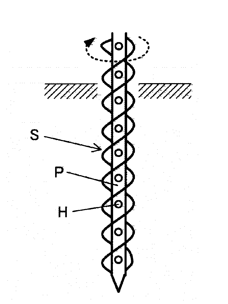
This patent describes a spiral piece of steel that can be twisted around a center axis to increase its mechanical strength. By placing two members with long sides around the center axis, the spiral piece of steel can be made stronger than traditional twisted steel plates. This design can also make the spacing between the twisted parts smaller without changing the twist angle. Additionally, the invention provides a hollow pipe that can be used in various applications, such as heat exchangers and pipes for discharging water. The hollow pipe can also have holes to allow for fluid movement. The thickness of the spiral piece of steel remains constant, preventing a decrease in mechanical strength. Finally, the invention provides a spiral steel pile that is strong against deformation in response to stress or compression in the lateral direction. This increases resistance against pulling force and allows for better contact with the ground.

Problems solved by technology

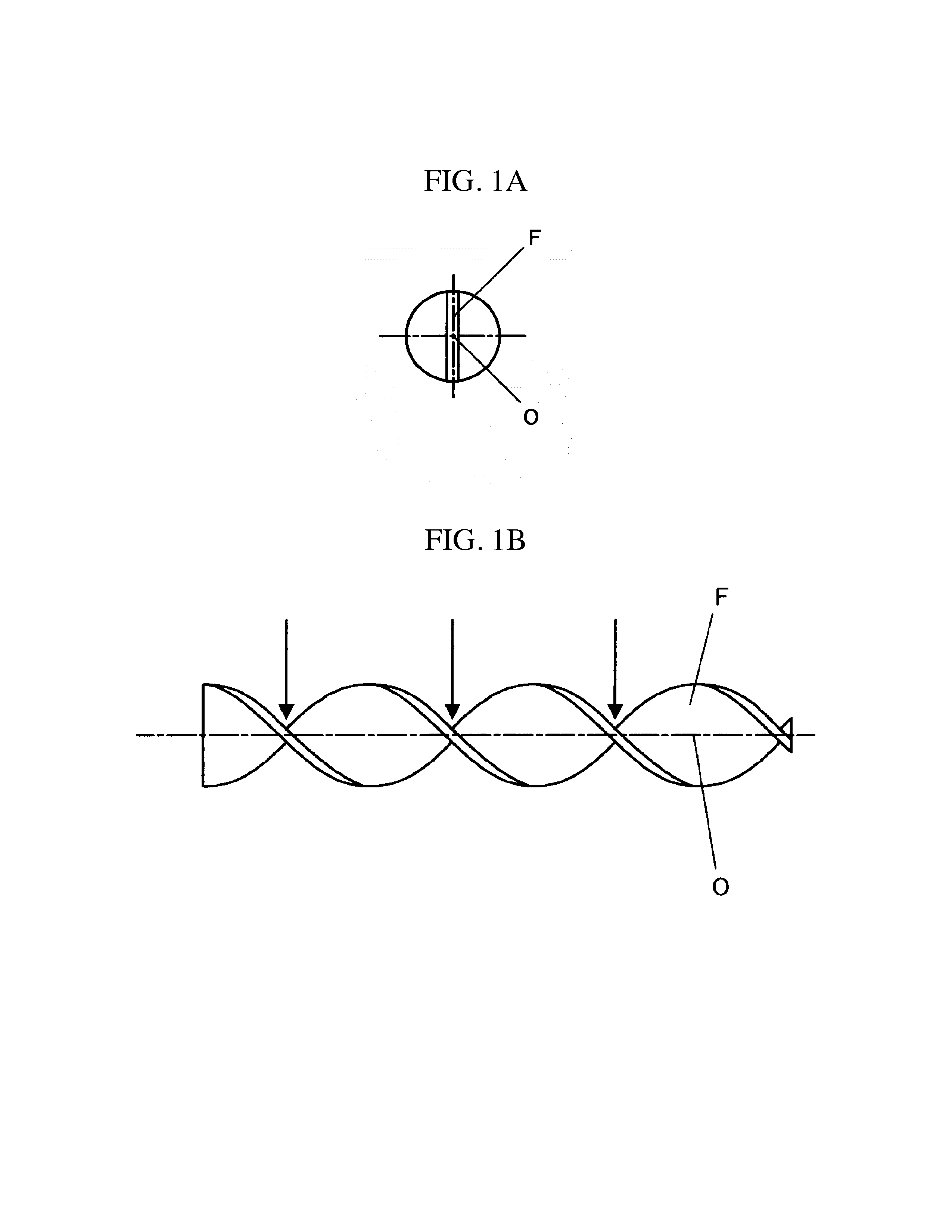
However, deformation can easily occur in the portions indicated by the arrows, for example, against pressure in the longitudinal direction of the twisted flat piece of steel or against a bending load applied in the upward and downward directions as in FIG. 1, and thus, sufficient mechanical strength cannot be gained.
Therefore, it is difficult to use twisted flat pieces of steel for supports of a structure where a problem arises such that it becomes difficult to process or the efficiency is low in the processing because secondary processing is required in order to increase the mechanical strength.
In addition, it may be extremely difficult to process a twisted flat piece of steel in the direction in which the pitch of the twisting of the flat piece is made smaller or compression buckling may be caused.

Method used


Image

  • Spiral steel, application product of same, and method for manufacturing spiral steel
  • Spiral steel, application product of same, and method for manufacturing spiral steel
  • Spiral steel, application product of same, and method for manufacturing spiral steel

Examples


Embodiment Construction

[0060]The spiral piece of steel according to the present invention, application products thereof and a method for manufacturing the spiral piece of steel are described in detail below.

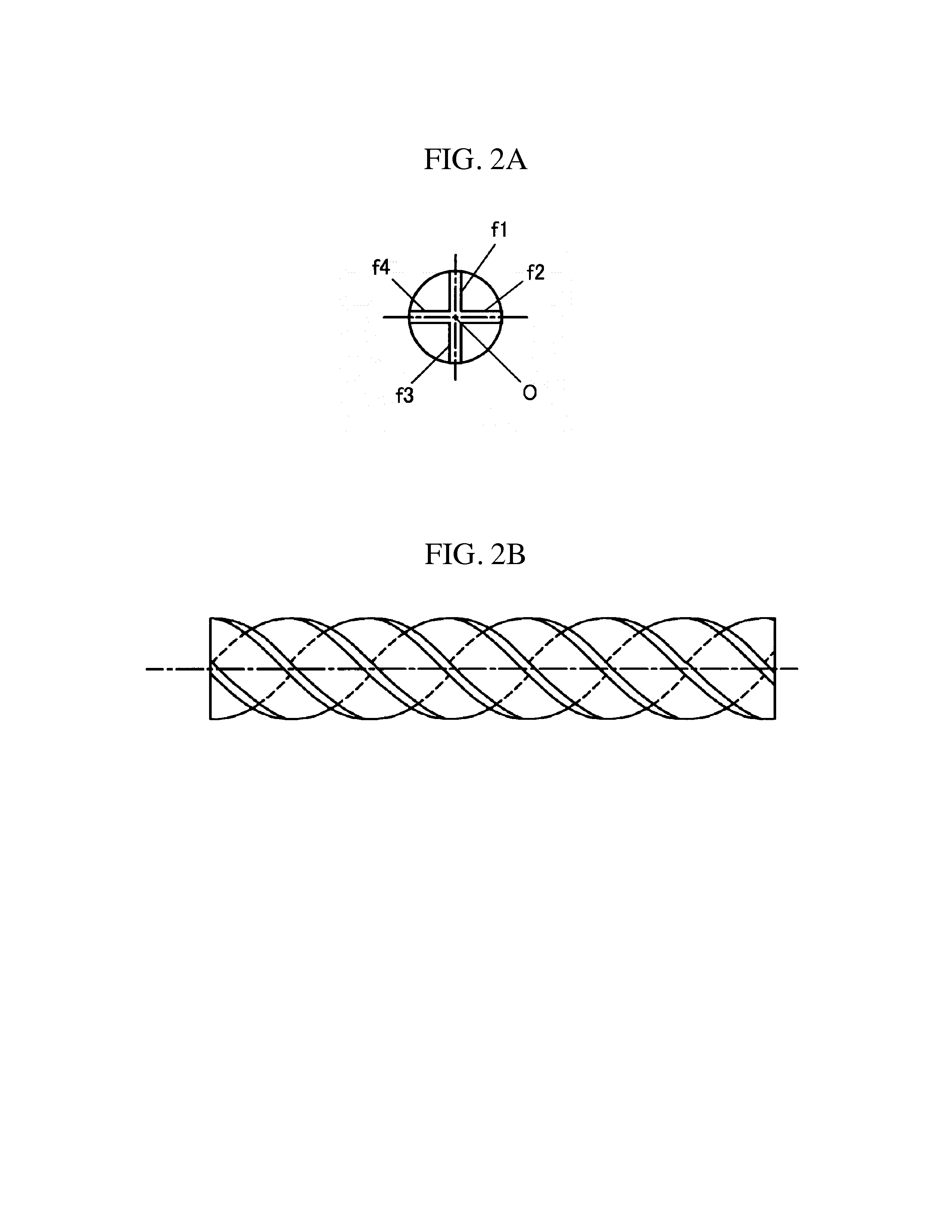
[0061]FIGS. 2(a) and 2(b) are diagrams for illustrating the spiral piece of steel according to the present invention.

[0062]The spiral piece of steel according to the present invention is formed by twisting a steel material around a center axis, where the center axis O is parallel to the longitudinal direction of the steel material, and at least three members with long sides (f1 to f4) are placed in radius form around the center axis O.

[0063]FIG. 2(a) is a cross-sectional diagram along a plane perpendicular to the longitudinal direction of the spiral piece of steel, and FIG. 2(b) is a side diagram showing the spiral piece of steel.

[0064]When the twisted steel plate in FIGS. 1(a) and 1(b) and the spiral piece of steel in FIGS. 2(a) and 2(b) are compared, the difference between the two is clear, and in pa...


PUM

PropertyMeasurementUnit
Mechanical strengthaaaaaaaaaa
Thicknessaaaaaaaaaa
Angleaaaaaaaaaa

Abstract

A purpose of the invention is to provide a spiral piece of steel having high mechanical strength and being capable of easily making smaller the pitch intervals of twisted portions (spiral blade portions) even without changing the twist angle, and also to provide an application product thereof and a method for manufacturing the spiral piece of steel.

Description

TECHNICAL FIELD[0001]The present invention relates to a spiral piece of steel formed by twisting a steel material in a certain form and an application product thereof as well as a method for manufacturing the spiral piece of steel.BACKGROUND ART[0002]Twisted flat pieces of steel have been conventionally used. The present applicant has proposed various applications of twisted flat pieces of steel that have been put into practice.[0003]Typical examples include piles driven into the ground for use as shown in Patent Document 1, supports where a steel pipe is joined to a twisted flat piece of steel so that rigidity is secured as shown in Patent Document 2, and anchors for preventing a cloth material from being lifted up (tent pegs) as shown in Patent Document 3. These piles can easily be installed through driving, and it is also possible to easily remove these by pulling them out while rotating.[0004]Other applications of twisted flat pieces of steel include drills for digging apparatus...

Claims


Application Information

Patent Timeline
IPC IPC(8): F16L9/02B21C47/02B65G33/26E02D5/80E21B10/00E02D5/28F28F1/00B01F7/00
CPCB21D11/14F28F1/00F28D7/103F28D7/106F28D7/12F28F1/36B21D53/02B01F7/00425F16L9/02E21B10/00E02D5/801E02D5/285B65G33/26B21C47/02F28F13/12E02D5/56B01F27/1144
Inventor GOTO, TSUNEO
Owner GOTO TSUNEO
Learn More