Lock for shelving assembly

Inactive Publication Date: 2008-12-11
NANCE DAVID W
View PDF51 Cites 20 Cited by
  • Summary
  • Abstract
  • Description
  • Claims
  • Application Information

AI Technical Summary

Benefits of technology

[0011]The distal end of the lock bar includes a lock tab extending normal thereto, i.e., toward the connector end component and underlying upright. The lock tab is preferably stamped and formed as an integral unit from the lock bar plate, and engages aligned holes through the connector end component and underlying upright. When the lock bar tab is so engaged, the tab prevents the connector end component from moving parallel to the underlying upright, thereby preventing the attachment pins of the connector end from disengaging from their seats within the upright passages and assuring that the shelving assembly remains assembled.

Problems solved by technology

One problem that can occur in such an environment is that the tines of the forklift may be placed inadvertently beneath the crossmember of the shelving structure, or perhaps for the pallet or other article to become caught on the shelving crossmember.
The result is the dropping of at least one end of the crossmember and all of the goods resting upon that shelf level, unless the forklift operator recognizes the problem in time and is able to get some assistance in reinstalling the crossmember.
Even so, the reinstallation of a shelving crossmember when the shelf is loaded is not a trivial task, and may prove to be impossible under the circumstances.

Method used


Image

  • Lock for shelving assembly
  • Lock for shelving assembly
  • Lock for shelving assembly

Examples


Embodiment Construction

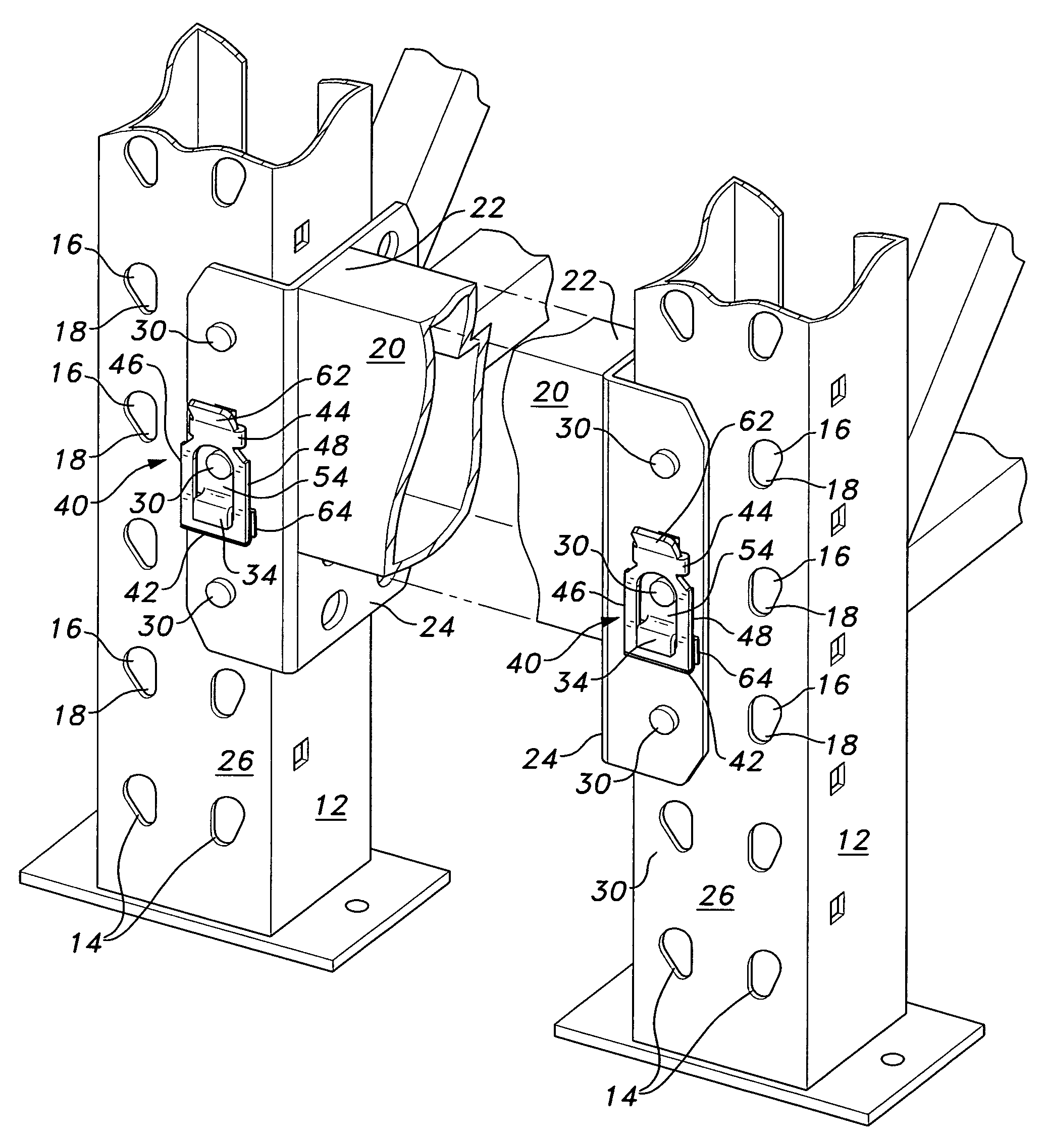
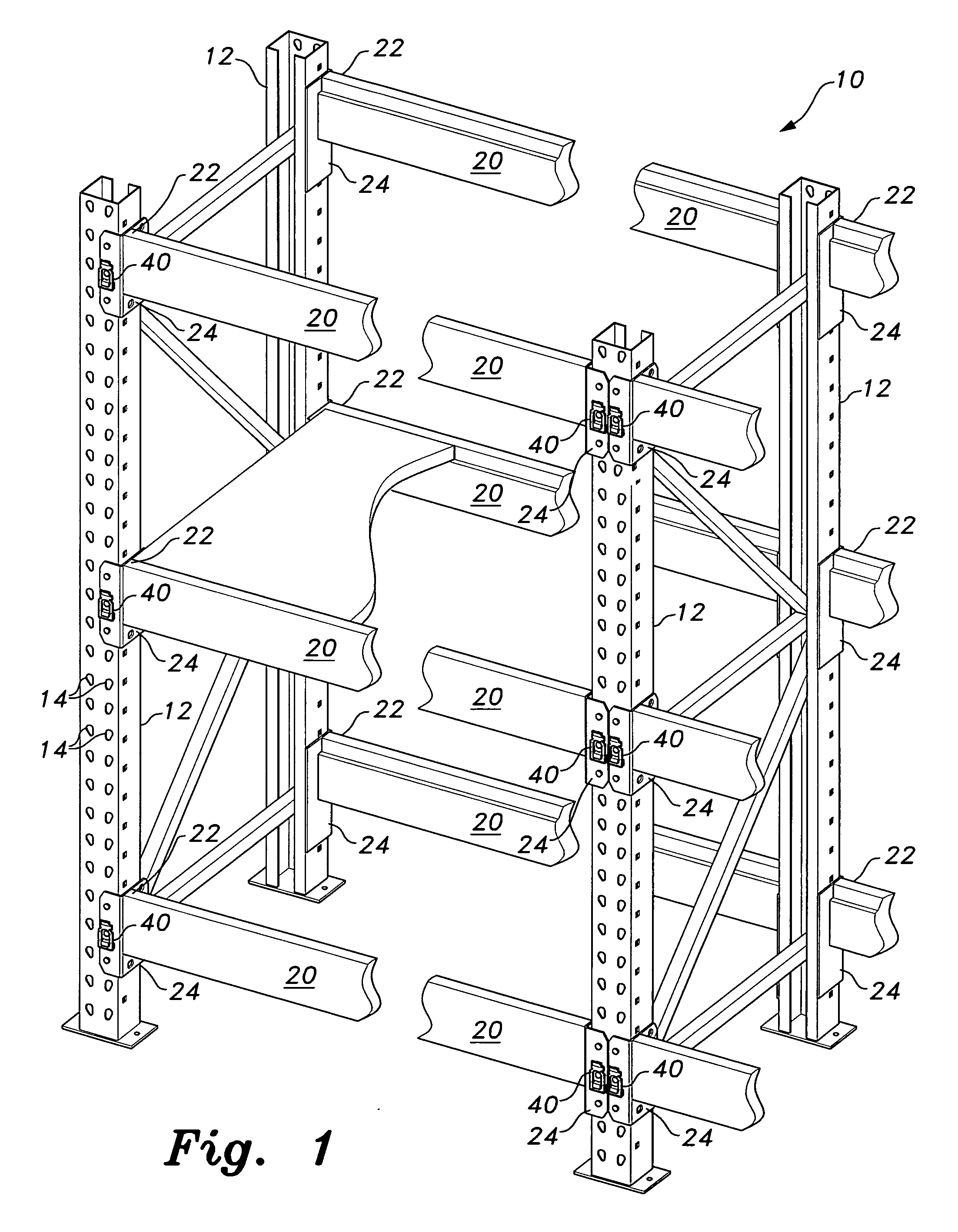
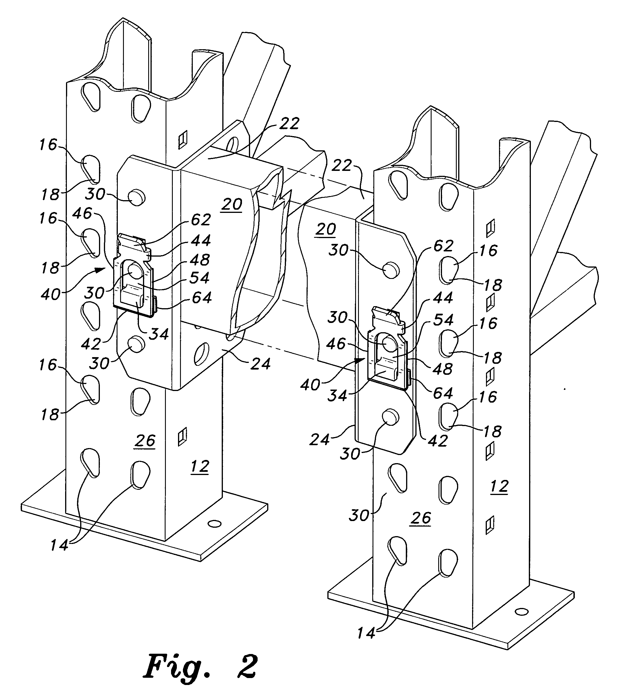
[0020]The present invention relates to various embodiments of a lock for a shelving assembly, assuring that the horizontal crossmembers or shelf support members cannot be lifted from their attachment to the standards or uprights of the assembly. FIG. 1 of the drawings provides an illustration of an exemplary shelving assembly 10, including a plurality of uprights 12 with horizontal crossmembers 20 secured between the uprights 12 and supporting one or more shelves thereon. The detail perspective view of FIG. 2 illustrates further details of this structure, showing the elongated connector pin passages 14 formed through each of the uprights 12.

[0021]Each of the connector pin passages 14 includes a relatively wider upper portion 16 dimensioned to allow the passage therethrough of the relatively wider head of the connector pin, and a relatively narrower lower portion 18 supporting the narrower shank of the pin therein and capturing the wider head of the pin therebehind. Each of the conne...


PUM


Abstract

The lock for a shelving assembly secures the connector ends of the horizontal members to the uprights of the assembly, preventing the horizontal members from being lifted from their attachments to the uprights. The lock comprises a rigid, inflexible lock bar having a peripheral frame surrounding a central passage therethrough, and an opposite distal end with a lock tab extending therefrom. The attachment edge of the lock bar frame is hooked upon a protruding lance tab of the connector end, with the lance tab serving as a hinge or fulcrum for the lock bar. A spring is wedged between the attachment edge of the lock bar frame and the adjacent connector end, urging the distal end of the lock bar toward the connector to engage the lock tab within aligned holes of the connector and upright to which it is attached.

Description

CROSS-REFERENCE TO RELATED APPLICATION[0001]This application claims the benefit of U.S. Provisional Patent Application Ser. No. 60 / 929,013, filed Jun. 8, 2007.BACKGROUND OF THE INVENTION[0002]1. Field of the Invention[0003]The present invention relates generally to shelving assemblies. More particularly, the present invention relates to a lock for a shelving assembly that fastens shelf components to standards or uprights having shelf bracket engagement openings formed therein, usually at spaced intervals, to lock the shelves at adjustable heights.[0004]2. Description of the Related Art[0005]Prefabricated shelving is in common use in many environments, e.g., warehouses and other storage facilities, so-called “big box” stores, etc. Such shelving generally have uprights and horizontal crossmembers, which have connector ends that attach removably to the uprights by pins fitting into cooperating slots in the uprights. The uprights generally include a large number of closely spaced slots,...

Claims


Application Information

Patent Timeline
IPC IPC(8): A47F5/00
CPCA47B57/50B65G1/02B65G2207/40F16B12/28
Inventor NANCE, DAVID W.
Owner NANCE DAVID W
Why Eureka
Try Eureka