Methods of measuring image-sticking of a display

a technology of image-sticking and display, which is applied in the field of measuring the phenomenon can solve the problems of inability to apply a method practically, inability to determine the level of image-sticking according to the brightness, and inability to accurately measure the level of image-sticking on the display

Inactive Publication Date: 2008-12-11
CHUNGHWA PICTURE TUBES LTD
View PDF6 Cites 13 Cited by
  • Summary
  • Abstract
  • Description
  • Claims
  • Application Information

AI Technical Summary

Benefits of technology

[0011]The present invention is directed to a method of measuring an image-sticking phenomenon of a display, which may accu

Problems solved by technology

Presently, the criterion and measuring standard of image-sticking levels are still not standardized due to improper measuring methods or impossible implementation of the measuring methods.
However, since the CCD cannot accurately simulate a sense of human eyes and cannot effectively quantify the sense, the method cannot be practically applied.
However, this method is susceptible to an interference of the color difference, and since the image-sticking phenomenon relates to an obvious degree of a boundary between different image-stick regions, the image-sticking level cannot be determined according to the brightness difference.
Th

Method used


Image

  • Methods of measuring image-sticking of a display
  • Methods of measuring image-sticking of a display
  • Methods of measuring image-sticking of a display

Examples


first embodiment

The First Embodiment

[0045]First, a display having N gray levels is provided. In an embodiment of the present invention, the display comprises a LCD. In another embodiment, the display comprises a plasma display panel.

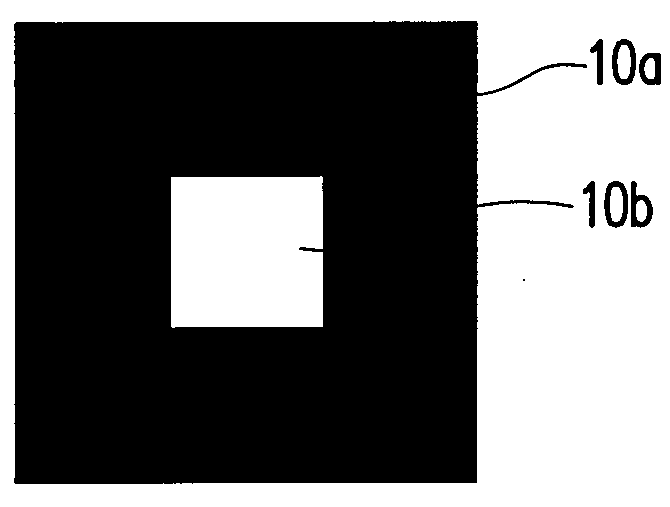
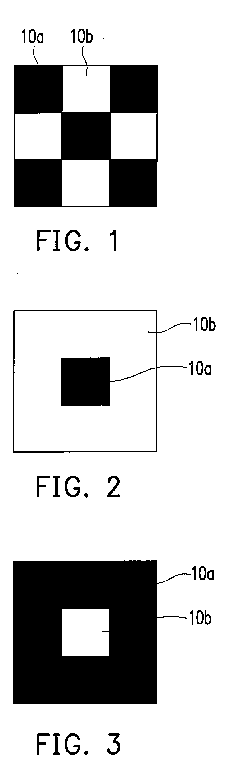
[0046]Next, an image-stick test frame is displayed on the display, as shown in FIG. 1, the image-stick test frame is composed of at least a first pattern 10a having a low gray level and at least a second pattern 10b having a high gray level. In an exemplary embodiment, the gray level of the first pattern 10a may be gray level 1, and the gray level of the second pattern 10b may be gray level N. Moreover, distributions of the first pattern 10a and the second pattern 10b of the image-stick test frame are diverse. For example, in an embodiment of the present invention, the distribution of the first pattern 10a and the second pattern 10b of the image-stick test frame comprises a chessboard distribution (shown as FIG. 1). In another embodiment, the first pattern 10a of the im...

second embodiment

The Second Embodiment

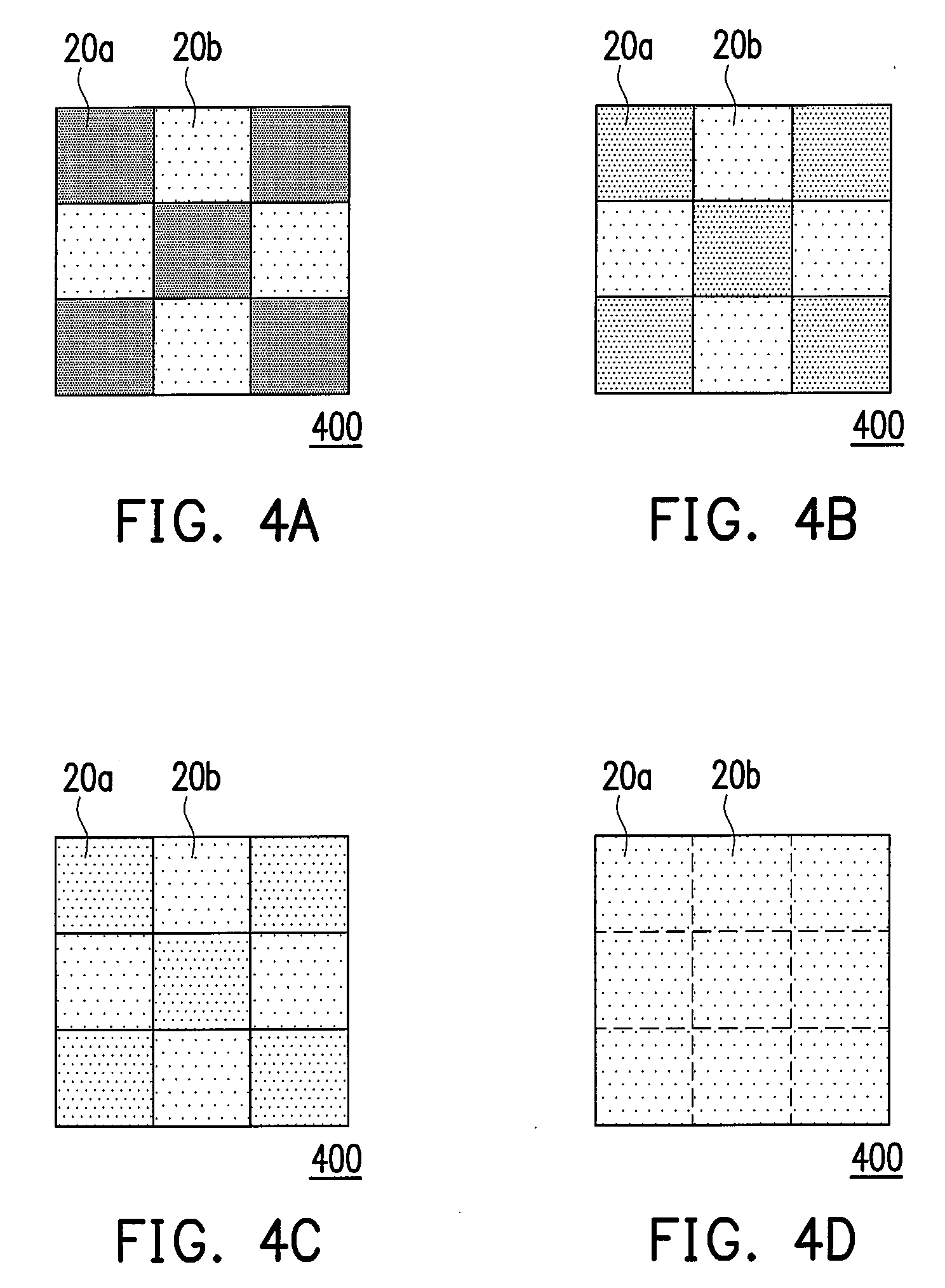
[0065]To improve the measuring accuracy of the image-sticking phenomenon of the displays, an optical measuring instrument (not shown) is further provided for judging whether the boundary of the images between the image-stick region 20a and the non-image-stick region 20b shown in FIGS. 4A˜4D is the lightest. The optical measuring instrument includes a luminance meter, a calorimeter and a spectrometer. The optical measuring instrument measures the images displayed on the image-stick region 20a and on the non-image-stick region 20b, and obtains a first value and a second value. When the first value and the second value are identical, the boundary of the images between the image-stick region 20a and the non-image-stick region 20b is the lightest (as shown in FIG. 4D).

[0066]In detail, if the optical measuring instrument is the luminance meter, the first value and the second value are brightness values. Thus, judging of the lightest boundary of the images between the ...

third embodiment

The Third Embodiment

[0067]Besides the measuring method described in the first and the second embodiments, the present embodiment provides another method for automatically measuring an image-sticking phenomenon, which will be described as follows. The present invention provides another method of measuring the image-sticking phenomenon of a display. First, a display having a plurality of pixels is provided. Next, an image-stick test frame is displayed on the display. As shown in FIG. 1, the image-stick test frame is composed of at least a first pattern and at least a second pattern 10b, wherein the gray level of the first pattern 10a is different from that of the second pattern 10b, or as describe in the first embodiment, the gray level of the first pattern 10a is gray level 1, and the gray level of the second pattern 10b is gray level N. In addition, it would be understood by those skilled in the art, arrangement of the image-stick test frames can be adjusted according to the actual ...


PUM


Abstract

A method of measuring image-sticking of a display is described. A display having N gray levels is provided. Next, an image-stick test frame having at least a first pattern having a low gray level and at least a second pattern having a high gray level is displayed on the display. After the image-stick test frame is displayed for a while, an image-stick region and a non-image-stick region are formed on the display. A measuring frame is then displayed on the display, wherein the non-image-stick region in the measuring frame has a standard gray level M. A plurality of middle gray levels is sequentially displayed on the image-stick region in the measuring frame. When the boundary between the non-image-stick region and the image-stick region in measuring frame is the lightest, the middle gray level is converted into an image-sticking level.

Description

CROSS-REFERENCE TO RELATED APPLICATION[0001]This application claims the priority benefits of Taiwan applications serial no. 96120714, filed on Jun. 8, 2007 and serial no. 96121870, filed on Jun. 15, 2007. All disclosures of the Taiwan applications are incorporated herein by reference.BACKGROUND OF THE INVENTION[0002]1. Field of the Invention[0003]The present invention relates to a method of measuring image-sticking phenomenon of a display. More particularly, the present invention relates to a method which may accurately measure an image-sticking level of a display.[0004]2. Description of Related Art[0005]Image-sticking is a phenomenon that an image or an outline of a previous static image appears in a next frame. Namely, when a static image is displayed on a screen for a relatively long time, it remains visible when the image is changed. Generally, the image-sticking phenomenon is observed by human eyes due to excessive brightness or color difference between an image-stick region an...

Claims


Application Information

Patent Timeline
IPC IPC(8): G09G3/36
CPCG09G3/006G09G3/20G09G3/3611G09G2320/0257G09G2360/147
Inventor LEE, CHIEN-PANGYANG, CHIEN-HUIHUANG, MING-WEIFU, MEI-CHICHIEN, PAI-CHUNG
Owner CHUNGHWA PICTURE TUBES LTD
Why Eureka
Try Eureka