Insulated surge suppression circuit

a surge suppression circuit and surge suppression technology, applied in the direction of emergency protective arrangements for limiting excess voltage/current, substation/switching arrangement casings, coupling device connections, etc., can solve the problem that nothing herein limits the use of our novel insulation system, and achieve the effect of flexibl

Active Publication Date: 2008-12-11
SURGE SUPPRESSION LLC
View PDF36 Cites 18 Cited by
  • Summary
  • Abstract
  • Description
  • Claims
  • Application Information

AI Technical Summary

Benefits of technology

[0019]A second glass fiber layer is then laid upon a top surface of first glass fiber layer such that the second glass fiber layer fills a majority of any resulting free space within the housing and up to a bottom surface of a top or lid portion, which seals the housing. In a preferred embodiment, the second glass fiber layer is a fiberglass padding (or “fluff”) that is generally more pliable than the woven first fiberglass layer.

Problems solved by technology

However, nothing herein limits the use of our novel insulation system with only enclosed surge suppression circuits.

Method used


Image

  • Insulated surge suppression circuit
  • Insulated surge suppression circuit
  • Insulated surge suppression circuit

Examples


Embodiment Construction

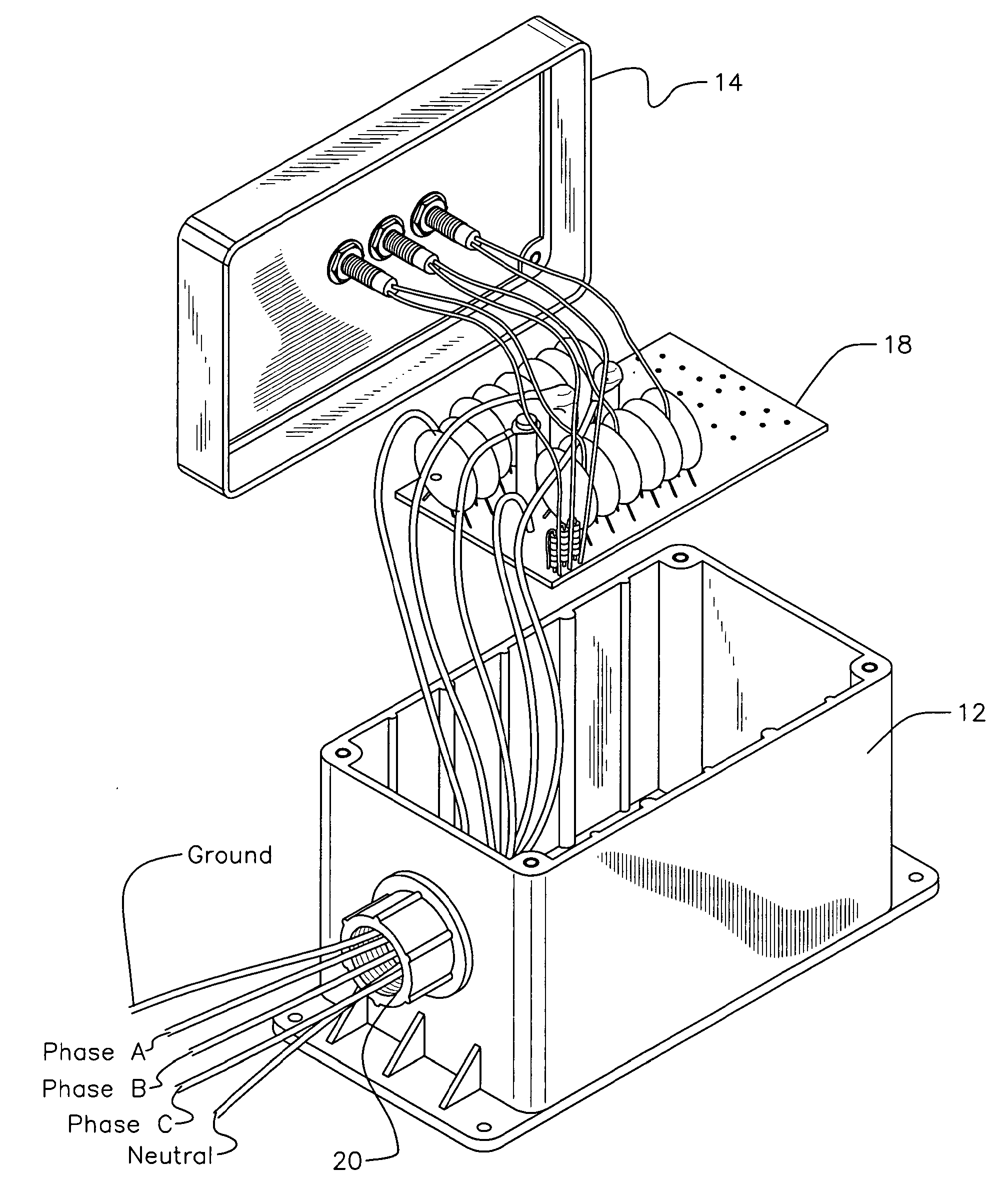
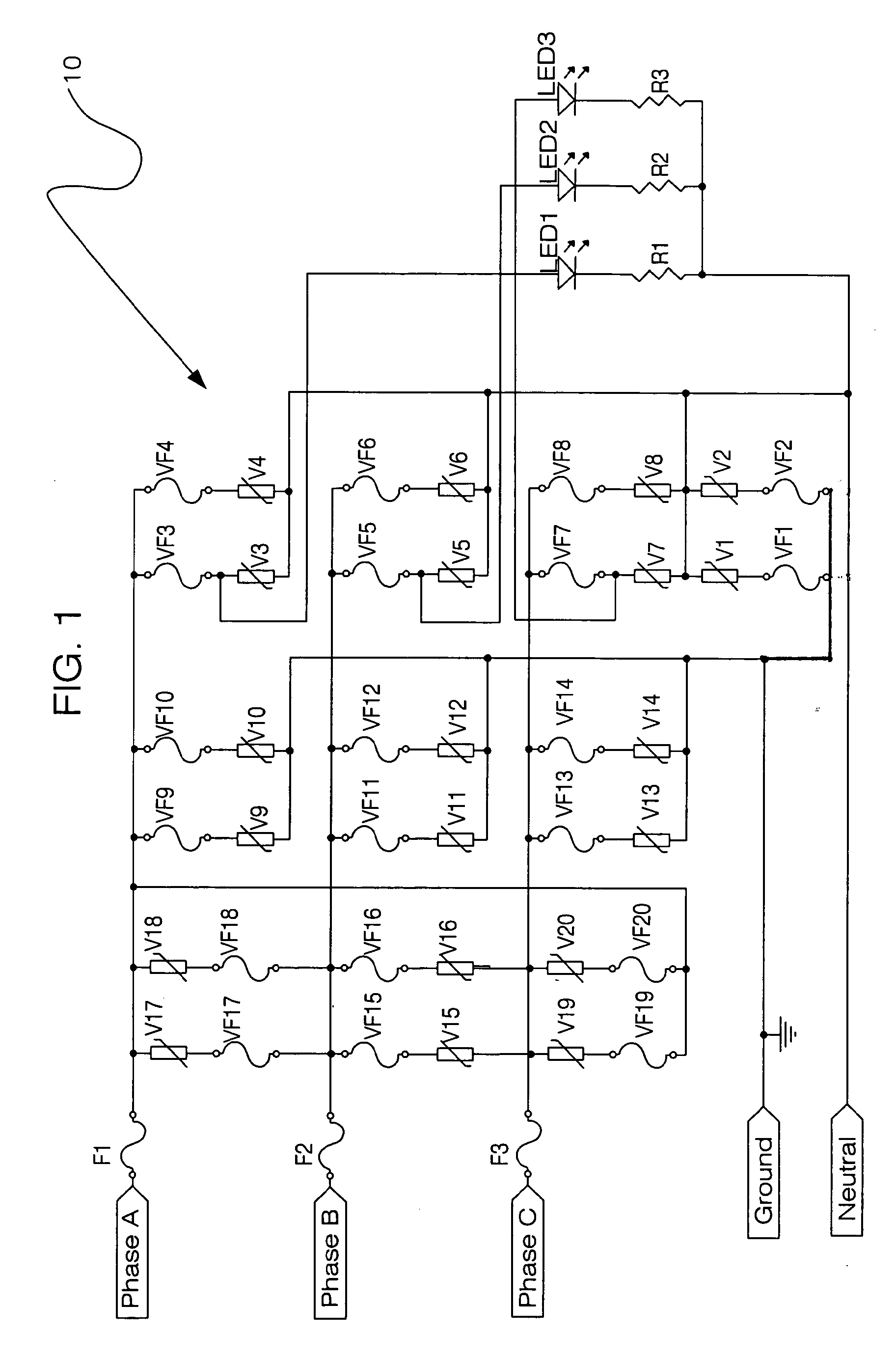
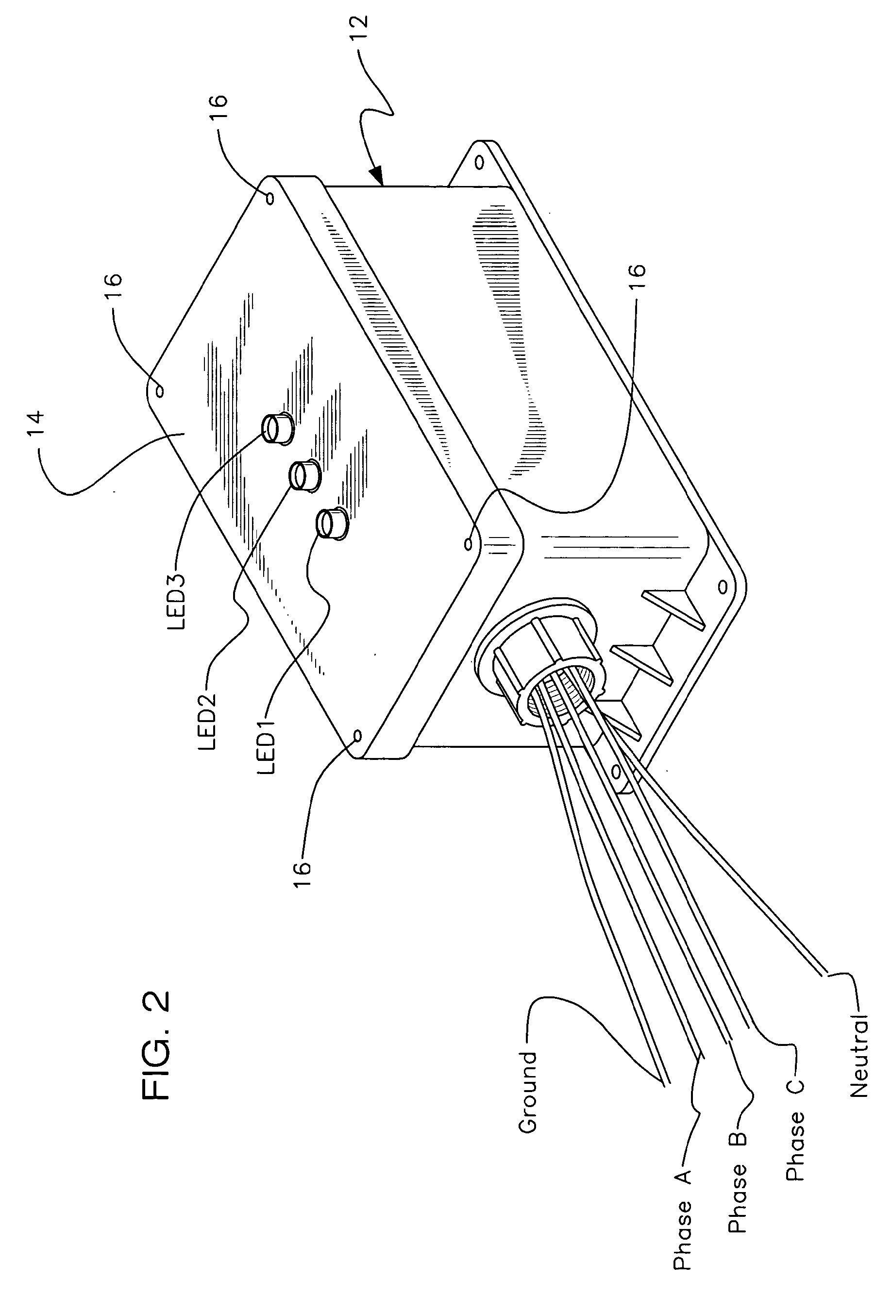
[0033]Throughout the following detailed description, the same reference numerals refer to the same elements in all figures.

[0034]Referring to FIG. 1, an electrical schematic diagram is shown illustrating a fused transient surge suppression circuit 10 employed with a transient voltage surge suppression device of the present invention. As shown, circuit 10 employs a plurality of Metal Oxide Varistors (MOVs) V1-V20 arranged in three columns (one for each phase of a three phase line) but electrically coupled in parallel. It is understood that nothing herein limits the use of this novel circuit with either single or two phase lines. It is further understood that any number of MOVs or like surge suppression components can be employed per column. Also, the number of columns can vary dependent upon the modes of protection for the surge suppression application. FIGS. 1-3 illustrate a preferred embodiment wherein a three phase line is employed having Phase A, Phase B, Phase C, Neutral and Gro...


PUM

PropertyMeasurementUnit
operating voltageaaaaaaaaaa
electricalaaaaaaaaaa
diametersaaaaaaaaaa

Abstract

A potted electrical circuit is enclosed within a housing and has a first and second fiberglass layer that is laid upon a top surface of the potted electrical circuit. A lid of the housing seals the electrical circuit there within and an opening formed in a side wall allows circuitry wiring to extend there from out. The first fiberglass layer is a woven layer while the second fiberglass layer is a padding-like layer. Circuitry wiring pushes through the woven first fiberglass layer before extending out through the opening in the housing. The first fiberglass layer is tucked in and around the electrical circuit and adheres to the inside of the housing by attaching to the potting material while it hardens. In a preferred embodiment, the electrical circuit in combination with the insulation material is used within a transient voltage surge suppression device.

Description

PRIOR APPLICATIONS[0001]This application is a Continuation-in-part of Ser. No. 11 / 003,828, filed on Dec. 3, 2004, now allowed, and Ser. No. 12 / 188,476, filed on Aug. 8, 2008, now pending.BACKGROUND OF THE INVENTION[0002]1. Field of the Invention[0003]The present invention relates to an apparatus for protecting electrical circuits from the effects of component product residue due to circuit failure. More particularly, it relates to an apparatus for protecting potted electrical circuits enclosed within housings that may typically employ surge suppression or other like circuitry used in the mitigation of electrical anomalies and abnormal conditions in devices to which the surge suppression circuitry is connected from component product residue that may be subjected upon surrounding circuitry when a failure of any particular circuit occurs.[0004]2. Description of the Prior Art[0005]Component failure on circuit boards of all types is very well known in the prior art. Some component failur...

Claims


Application Information

Patent Timeline
Patent Type & Authority Applications(United States)
IPC IPC(8): H02H3/22H05K7/00
CPCH02H9/042H02H9/044H05K1/0257H05K3/284H05K5/064Y10T29/49158H05K2201/029Y10T29/49146Y10T29/49126Y10T29/49117H05K9/0066B29C39/00H01C7/12
Inventor HOTCHKISS, RONALDHOTCHKISS, JR., RICHARDFUSSELL, RICKYHAA, ANDREA
Owner SURGE SUPPRESSION LLC
Why Eureka
Try Eureka