
Arithmetic device and arithmetic method

Inactive Publication Date: 2008-12-11
FUJITSU LTD
View PDF5 Cites 6 Cited by
  • Summary
  • Abstract
  • Description
  • Claims
  • Application Information

AI Technical Summary

Benefits of technology

[0024]It is an object of the present invention to at least

Problems solved by technology

Thus, the floating point addition / subtraction and the floating point multiplication are not performed efficiently.

Method used


Image

  • Arithmetic device and arithmetic method
  • Arithmetic device and arithmetic method
  • Arithmetic device and arithmetic method

Examples


Embodiment Construction

[0034]Exemplary embodiments of an arithmetic device and an arithmetic method according to the present invention are described below in detail with reference to the drawings. The present invention is not limited to the embodiments.

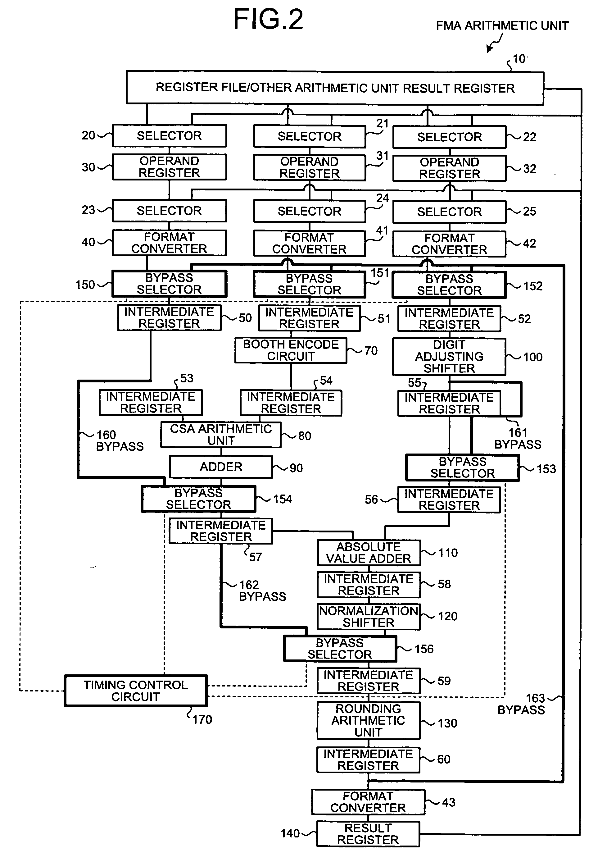
[0035]The present invention shortens an arithmetic latency in floating point addition / subtraction and floating point multiplication in a floating point multiplication and addition arithmetic unit (i.e., FMA arithmetic unit) and in executing an arithmetic operation using a result of previous arithmetic operation as an operand in the FMA arithmetic unit, by bypassing a redundant part of the FMA arithmetic unit.

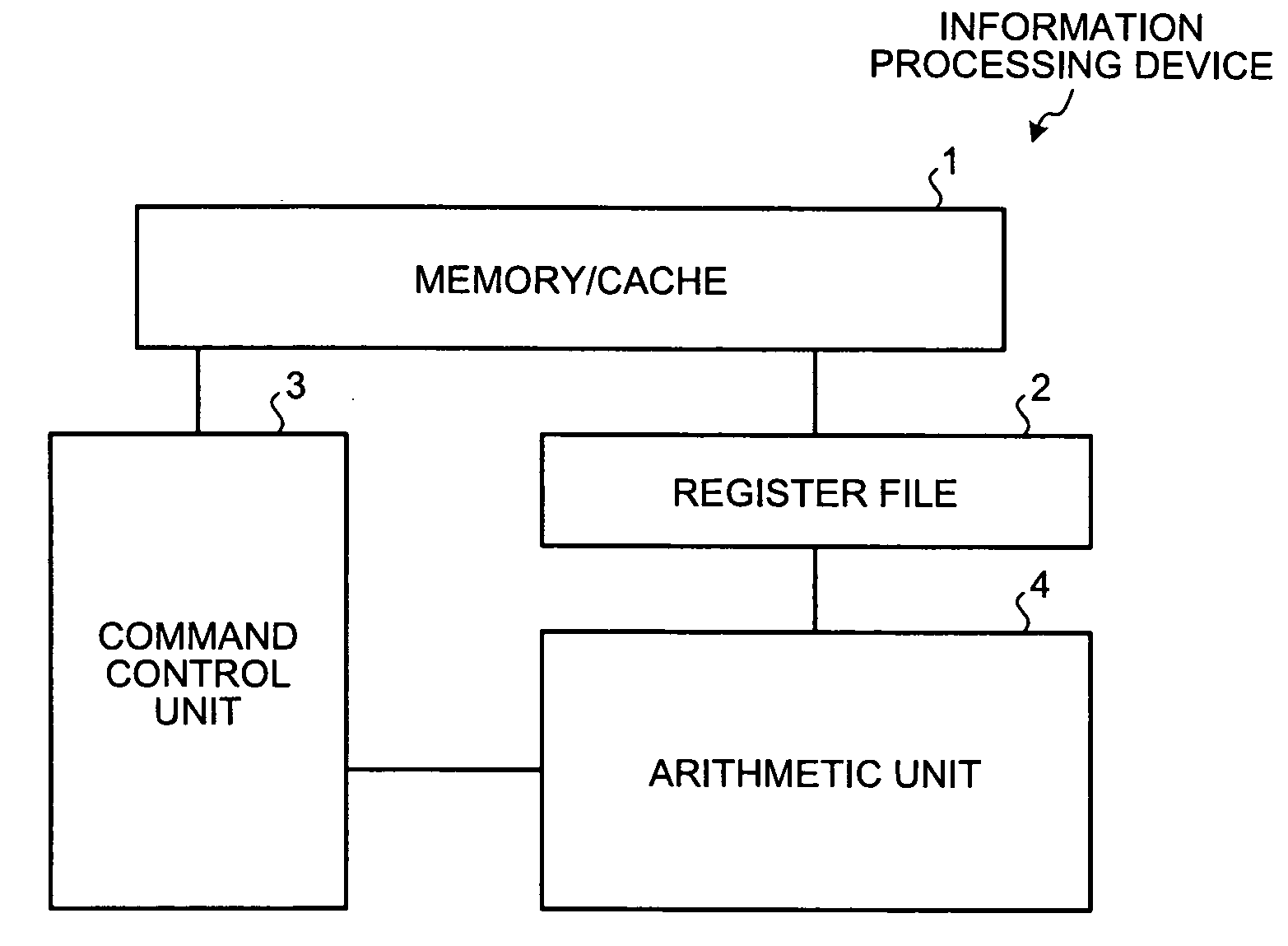
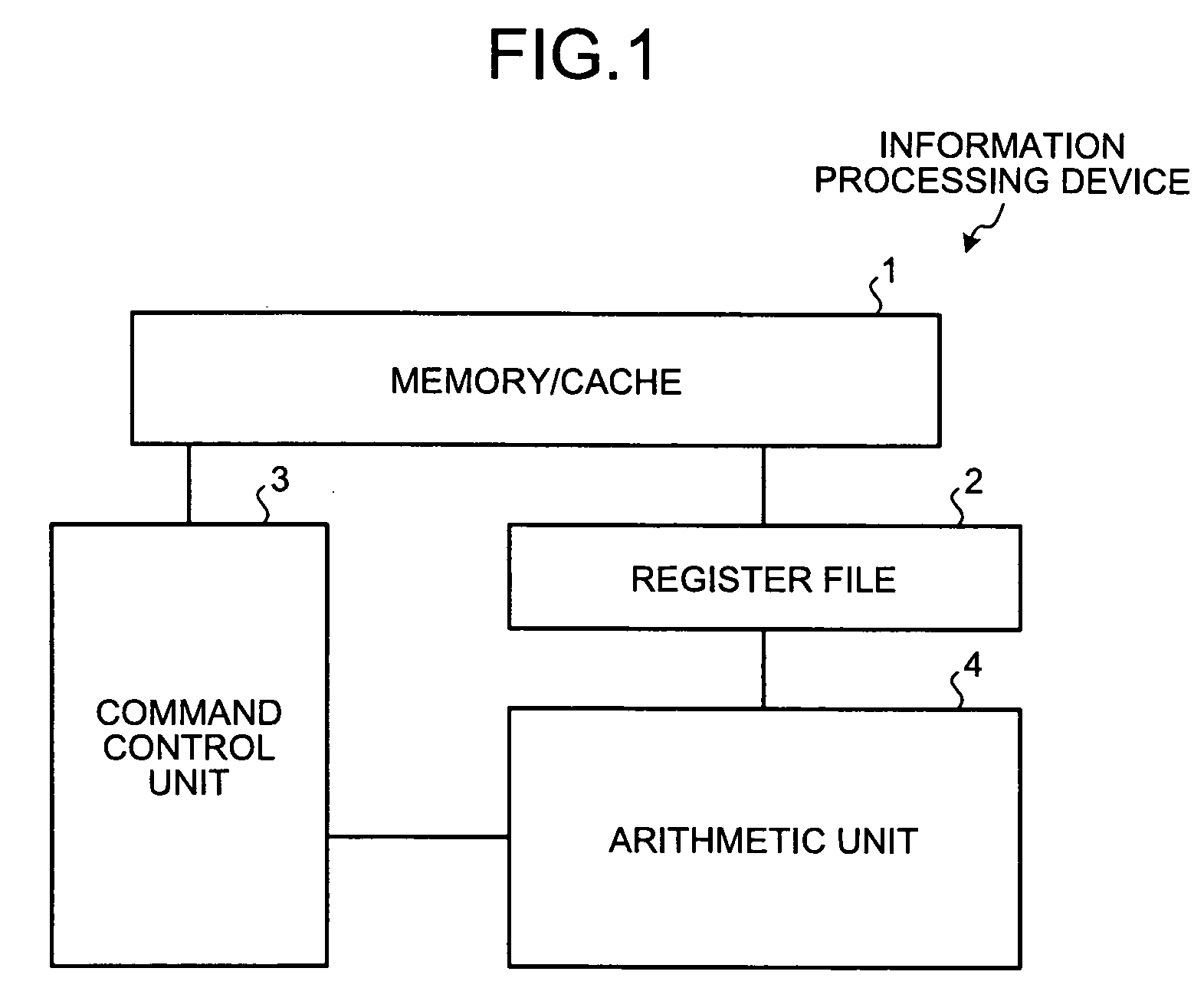
[0036]FIG. 1 is a diagram of a configuration of an information processing device including an FMA arithmetic unit according to the embodiment of the present invention. As shown in FIG. 1, the information processing device has a memory / cache 1, a register file 2, a command control unit 3, and an arithmetic unit 4. Of these, the memory / cache 1 is a device...


PUM


Abstract

An FMA arithmetic unit has a timing control circuit. The timing control circuit controls bypass selectors to bypass intermediate resisters on performing floating point addition / subtraction, controls another bypass selector to bypass another intermediate register on performing floating point multiplication, and controls still another bypass selectors to bypass a register file / other arithmetic unit result register and operand registers on performing successive FMA arithmetic operations.

Description

BACKGROUND OF THE INVENTION[0001]1. Field of the Invention[0002]The present invention relates to an arithmetic device which performs addition, subtraction, and multiplication of numbers represented by floating points and an arithmetic method thereof.[0003]2. Description of the Related Art[0004]In recent years, due to rapid spread of multimedia, TV games using delicate graphics, and the like, or other reasons, it is required to provide a customer with high-quality computer graphics and the like used in multimedia, TV games, and the like.[0005]In order to meet such a demand, realization of a high-speed floating point multiplication and addition arithmetic unit is desired. A configuration of a conventional floating point multiplication and addition arithmetic unit (referred to below as “FMA arithmetic unit”) is explained below in a concrete manner. FIG. 6 is a block diagram of the conventional FMA arithmetic unit.[0006]As shown in FIG. 6, the FMA arithmetic unit is provided with a regi...

Claims


Application Information

Patent Timeline
IPC IPC(8): G06F7/42G06F7/44
CPCG06F7/483G06F2207/3868
Inventor KAN, RYUJI
Owner FUJITSU LTD
Learn More