Method for Removing Anode Residues Attached to Spent Anodes Coming from Melt Bath Electrolysis Potlines
- Summary
- Abstract
- Description
- Claims
- Application Information
AI Technical Summary
Benefits of technology
Problems solved by technology
Method used
Image

Examples
Embodiment Construction
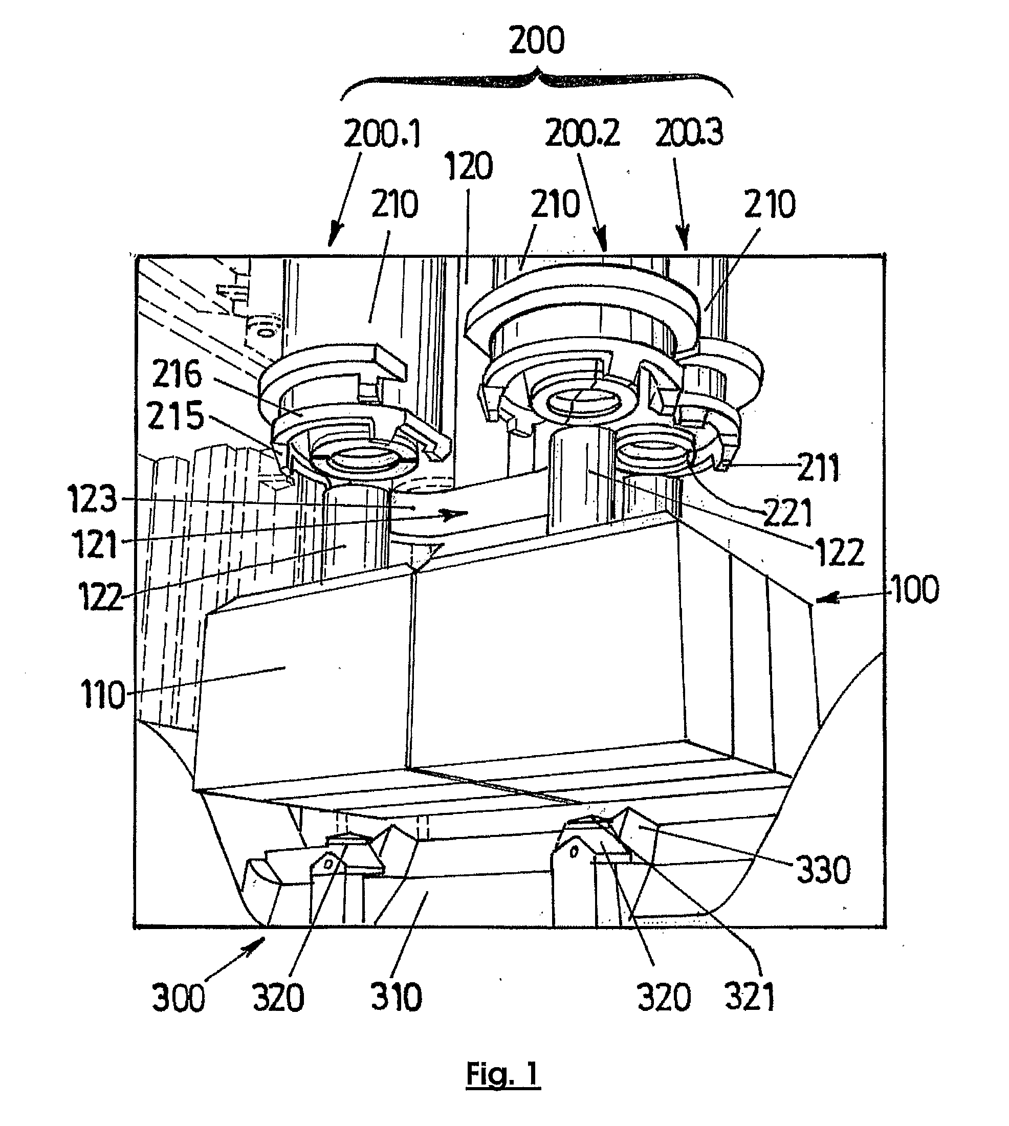
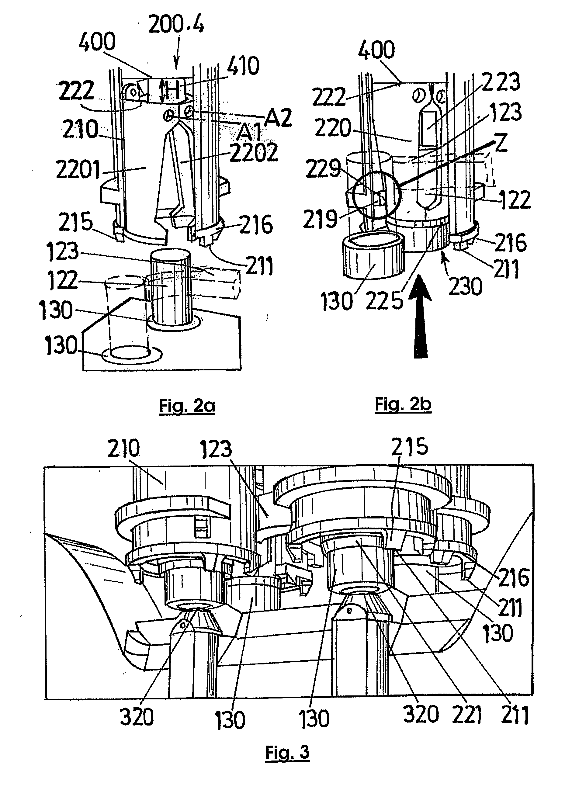
[0011]A first subject according to the invention is a process making it possible to extract the anode butt and thimbles stuck to a spent anode, including the following stages:[0012]a) the butt of the spent anode is placed between a stop device and an attacking device, said attacking device being able to be moved by means of an actuator towards said stop device, said stop device surrounding, at least partially, each stub of the anode stem leg and having a first stop preventing the butt from moving forward, said stop device being provided, around each stub, with a recess with a second stop which prevents said thimbles from moving forward;[0013]b) the spent anode is moved until the butt is blocked by the first stop;[0014]c) the attacking device is moved towards the stop device so that it arrives in contact with said anode butt and imposes on said butt such a force as to cause it to break up and the fragments to be detached from the butt;[0015]d) the fragments of butt are removed;[0016]...
PUM
| Property | Measurement | Unit |
|---|---|---|
| Thickness | aaaaa | aaaaa |
| Diameter | aaaaa | aaaaa |
| Ratio | aaaaa | aaaaa |
Abstract
Description
Claims
Application Information
 - R&D
- Intellectual Property
- Life Sciences
- Materials
- Tech Scout
- Unparalleled Data Quality
- Higher Quality Content
- 60% Fewer Hallucinations
Browse by: Latest US Patents, China's latest patents, Technical Efficacy Thesaurus, Application Domain, Technology Topic, Popular Technical Reports.
© 2025 PatSnap. All rights reserved.Legal|Privacy policy|Modern Slavery Act Transparency Statement|Sitemap|About US| Contact US: help@patsnap.com