Lubrication System and Internal Combustion Engine Comprising Such a System

a technology of lubrication system and internal combustion engine, which is applied in the direction of pressure lubrication, machines/engines, mechanical equipment, etc., can solve the problems of complex system, high cost, and waste of power

Inactive Publication Date: 2008-12-18
RENAULT TRUCKS
View PDF7 Cites 23 Cited by
  • Summary
  • Abstract
  • Description
  • Claims
  • Application Information

AI Technical Summary

Problems solved by technology

With such a system, one- can bypass the pump under certain circumstances but the pump works at a constant pace, which means that some power is wasted.
The system is complex and, therefore, quite expensive.

Method used


Image

  • Lubrication System and Internal Combustion Engine Comprising Such a System
  • Lubrication System and Internal Combustion Engine Comprising Such a System
  • Lubrication System and Internal Combustion Engine Comprising Such a System

Examples


Embodiment Construction

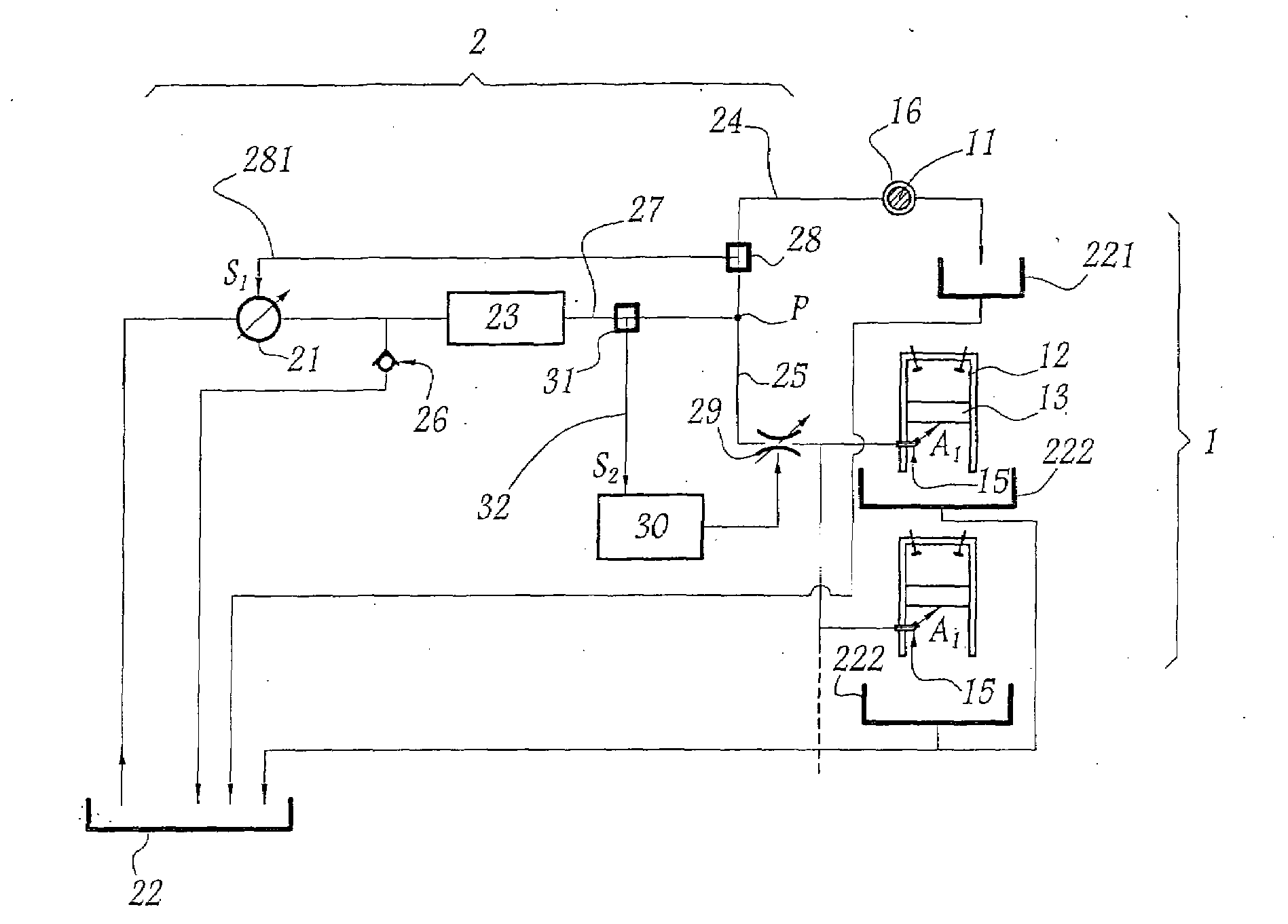
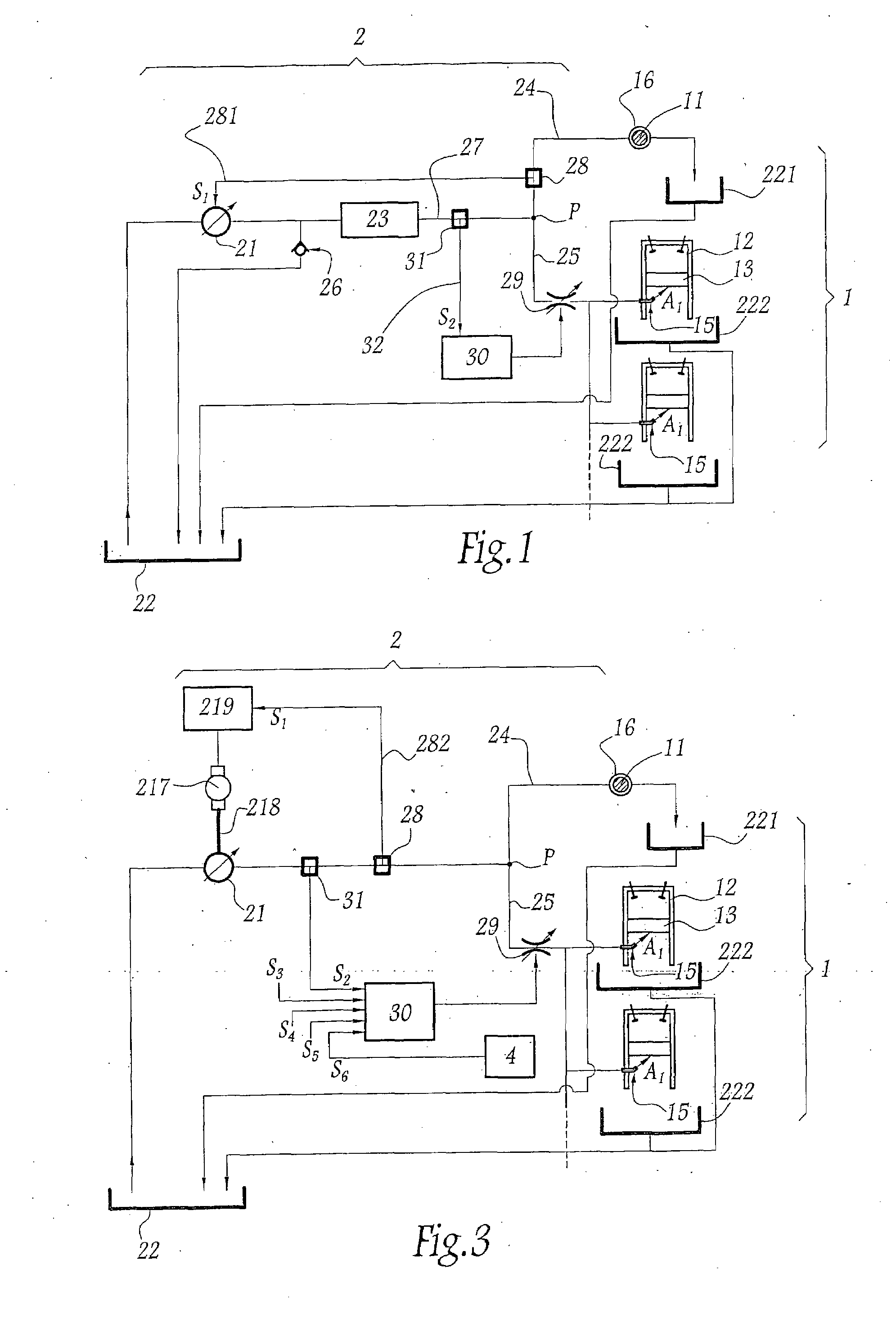
[0022]The lubrication system represented on FIG. 1 is adapted to be mounted onto an internal combustion engine 1 which comprises a crank shaft 11 and several cylinders 12, only two cylinders being represented. A piston 13 is slidably movable within each cylinder 12, between a top dead center position and a bottom dead center position represented on FIG. 1. A piston cooling jet 15 is provided for each cylinder 12 and is adapted to direct a flow of oil towards its piston 13 in its bottom dead center position, as represented by arrows Ai on FIG. 1.

[0023]Crank shaft 11 is supported by several bearings 16. Only one bearing is represented on FIG. 1. Oil is to be fed to each interface between a bearing 16 and crank shaft 11.

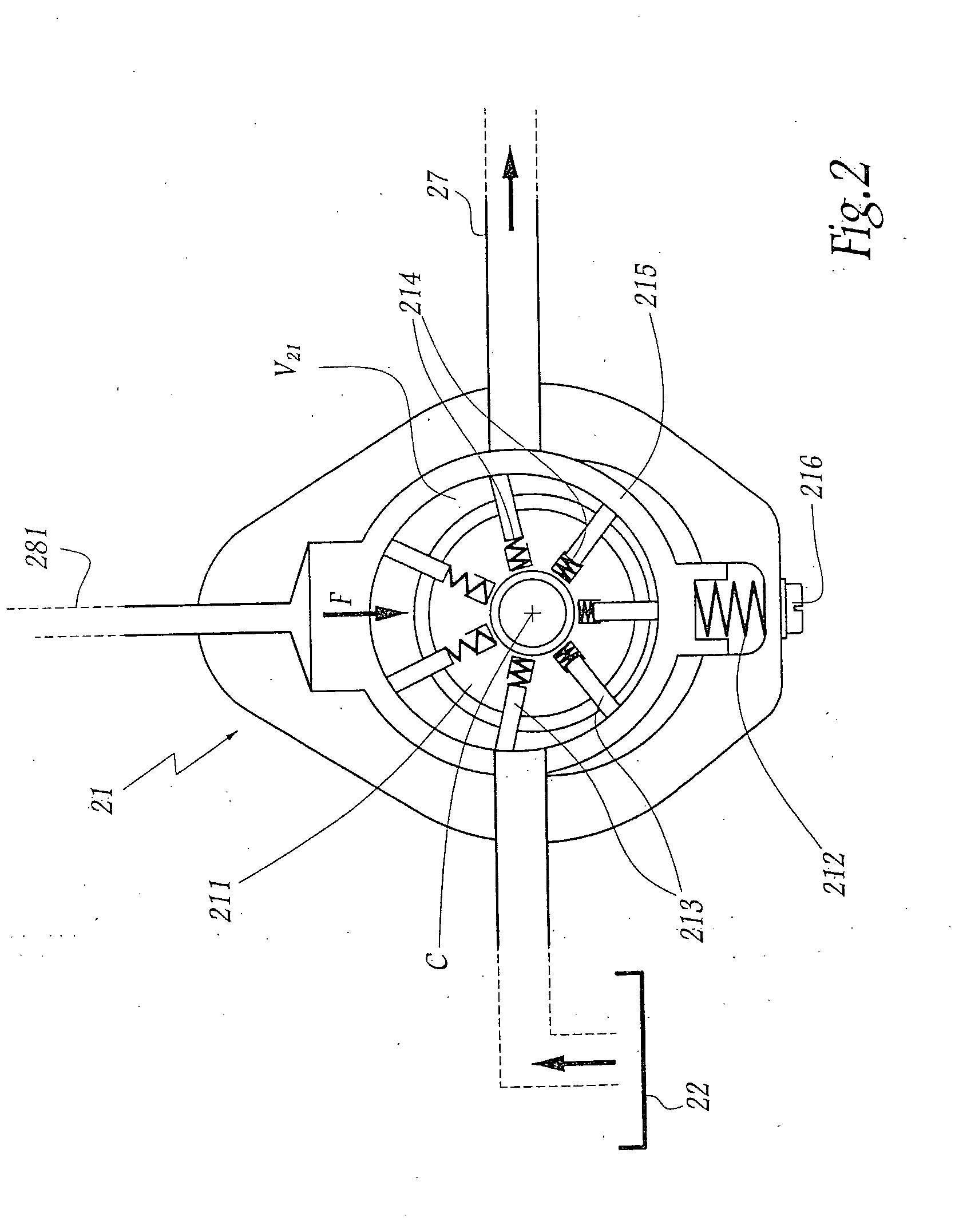
[0024]To this purpose, a lubrication system 2 includes a vane pump 21 adapted to suck oil from a sump and to feed a heat exchanger 23 which, itself, feeds two lines, namely a first line 24 feeding the interface between crank shaft 11 and at least one bearing 16 and a se...


PUM


Abstract

This lubrication system includes a pump feeding a main line which provides oil to a support interface for a crank shaft of oil engine and an auxiliary line connected to at least one piston cooling jet. The pump is a variable flow pump controlled on the basis of oil pressure in the main line. A proportional means is mounted on the auxiliary line. This means is adapted to control oil flow in the auxiliary line depending on the working conditions of the engine, e.g. oil temperature, torque to be delivered or rotational speed of the engine.

Description

BACKGROUND AND SUMMARY[0001]This invention concerns a lubrication system for an internal combustion engine. It also concerns an internal combustion engine including at least such one system.[0002]In order to lubricate moving parts of an internal combustion engine, it is known to use a pump which feeds oil to different locations in the engine. In order to determine the capacity of such a pump, one generally considers a standard working condition of the engine, e.g. the torque point of the engine, that is the working condition of the engine at 1000 rpm. However, depending on the actual rotational speed of the engine on the torque to be delivered, on the temperature of the oil, etc . . . the working conditions of the pump may vary to a great extent. It is therefore known, e.g. from WO-A-2004 / 065765, to use an oil pump controlled via a pressure-sensing means acted on by the working pressure of the oil. With such a system, one- can bypass the pump under certain circumstances but the pump...

Claims


Application Information

Patent Timeline
Patent Type & Authority Applications(United States)
IPC IPC(8): F01M1/04
CPCF01M1/16F01M2001/0215F01M2001/0246F01P3/08F04C14/223
Inventor AIXALA, LUC
Owner RENAULT TRUCKS
Why Eureka
Try Eureka