Hydraulically prestressed elastomer spring element and the use thereof in wind turbine bearings

a technology of elastomer spring element and wind turbine bearing, which is applied in the field of spring element and bearing, can solve the problems of indeterminate support resulting from four bearing points, damage to the turbine, and material or individual components damage, so as to achieve the effect of adjusting the volume of the recess or the cavity (4) and a wide range of stiffness

Active Publication Date: 2008-12-18
FM ENERGIE GMBH& CO KG
View PDF1 Cites 39 Cited by
  • Summary
  • Abstract
  • Description
  • Claims
  • Application Information

AI Technical Summary

Benefits of technology

[0018]Furthermore, it has been found that the sealing is particularly advantageous, stable and complete if a prestressing free space (10c) is provided between the pressure-increasing element (6) and the elastic bead (10) of the pressure membrane, which free space can be formed by a corresponding, preferably wedge-shaped, recess in the material of the sealing elements or the corresponding parts of the hydraulic device.
[0033]In particular, the invention also relates to corresponding spring elements in which the elastomer layers (1) have, in the core of the spring element, a conical cavity which is shaped in a manner corresponding to the membrane cavity (12) and is filled by the conical membrane cap (12a) formed by the pressure membrane. Such spring elements can be modified in such a way that the membrane cavity (12) of the conical pressure membrane cap (12a) has a stop device (50) which, in the event of overloading of the system, prevents the conical pressure membrane from irreversibly collapsing. Such a stop device is produced from a nonelastic material, preferably in the form of a conical cap which is arranged centrally in the interior of the membrane cavity (12) on the base of the membrane head (12a) and has a supply conduit and a connection to the hydraulic supply line (4). The supply conduit can also be designed in the form of an annular gap.
[0035]In these cases, a spring element of this type can be fitted in such a way that it has, on the side opposite the hydraulic device, a recess or cavity (40) in the elastomer material in the core region of the spring element, which recess or cavity is shaped and configured in such a way that it is separated from the membrane space (12) by means of a web (42) of elastomer material of the layers (1), so that the web can be pushed into the cavity or the recess when the hydraulic pressure in the membrane space increases. As a result, a greater range of adjustment of the stiffness is possible, particularly if the recess or cavity (40) additionally has a nonelastic calibration element (3, 8), with the aid of which the volume of the recess or the cavity (4) can be altered.

Problems solved by technology

In the case of large wind turbines with outputs of more than two megawatts, strong forces quite often act, in particular, on the rotor blades, rotor shaft and drive-train bearing arrangement, but also on the 
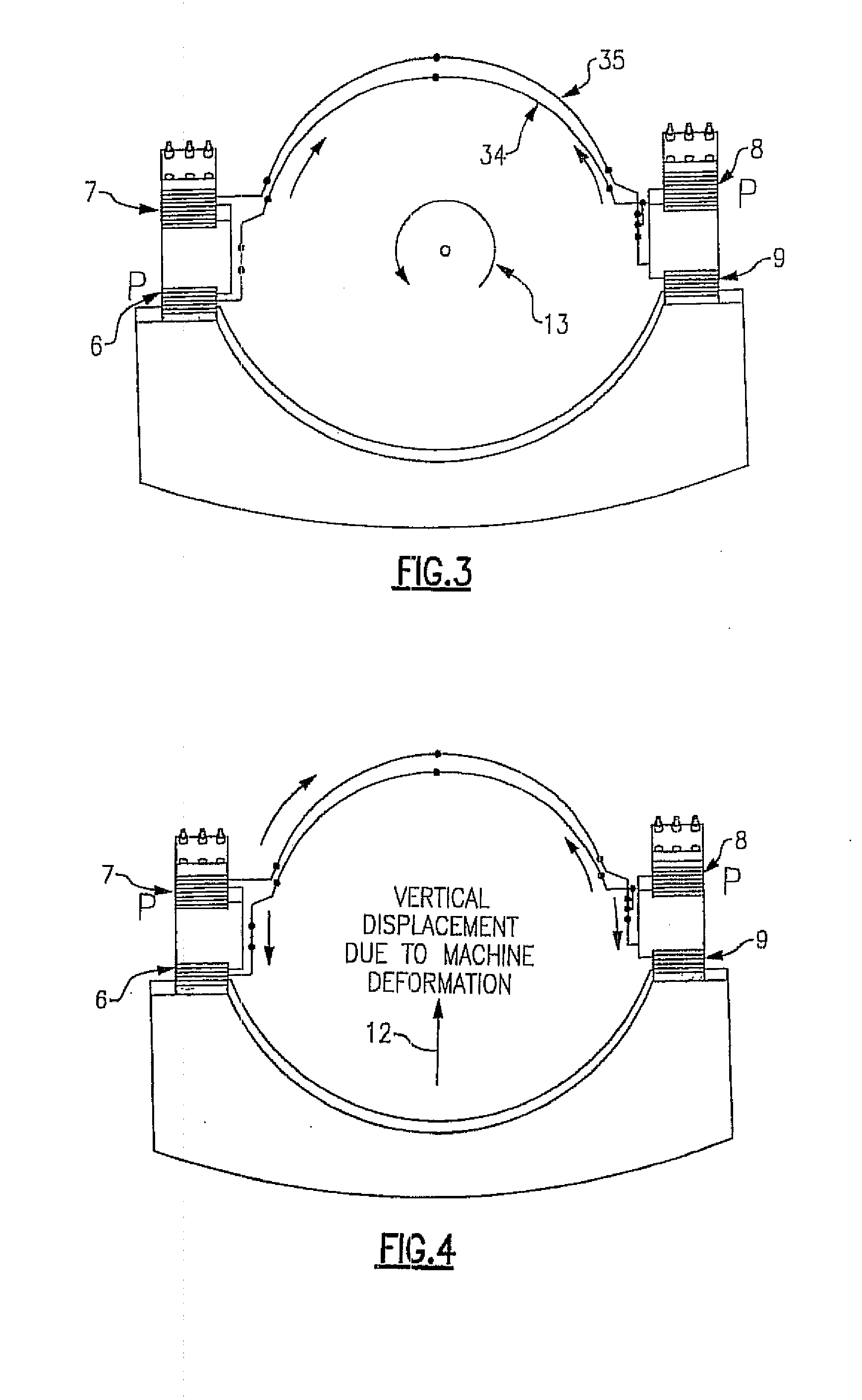
nacelle itself, and these forces subject the two-, three- or four-point bearings usually used for the gearboxes and generators to great loads, meaning that corresponding, in particular also vertical, displacements, deformations, distortions and pitch movements of the turbine can result, possibly with damage to the material or individual components.
In the event of very high, in particular suddenly and rapidly occurring loads (extreme load case) especially in the vertical direction, i.e. normally in the direction in which the elastomer spring elements with the usual arrangement have high spring stiffness, the elasticity or stiffness of these elements, which, with respect to their adjustable stiffness, are generally designed for average loads and normally applied forces, in particular on the drive-train bearing arrangement, is not sufficient, so that the aforementioned deformations, displacements and distortions which occur in the turbine lead to damage to the turbine, especially to the gearbox, as described in more detail below.
The disadvantage of this 
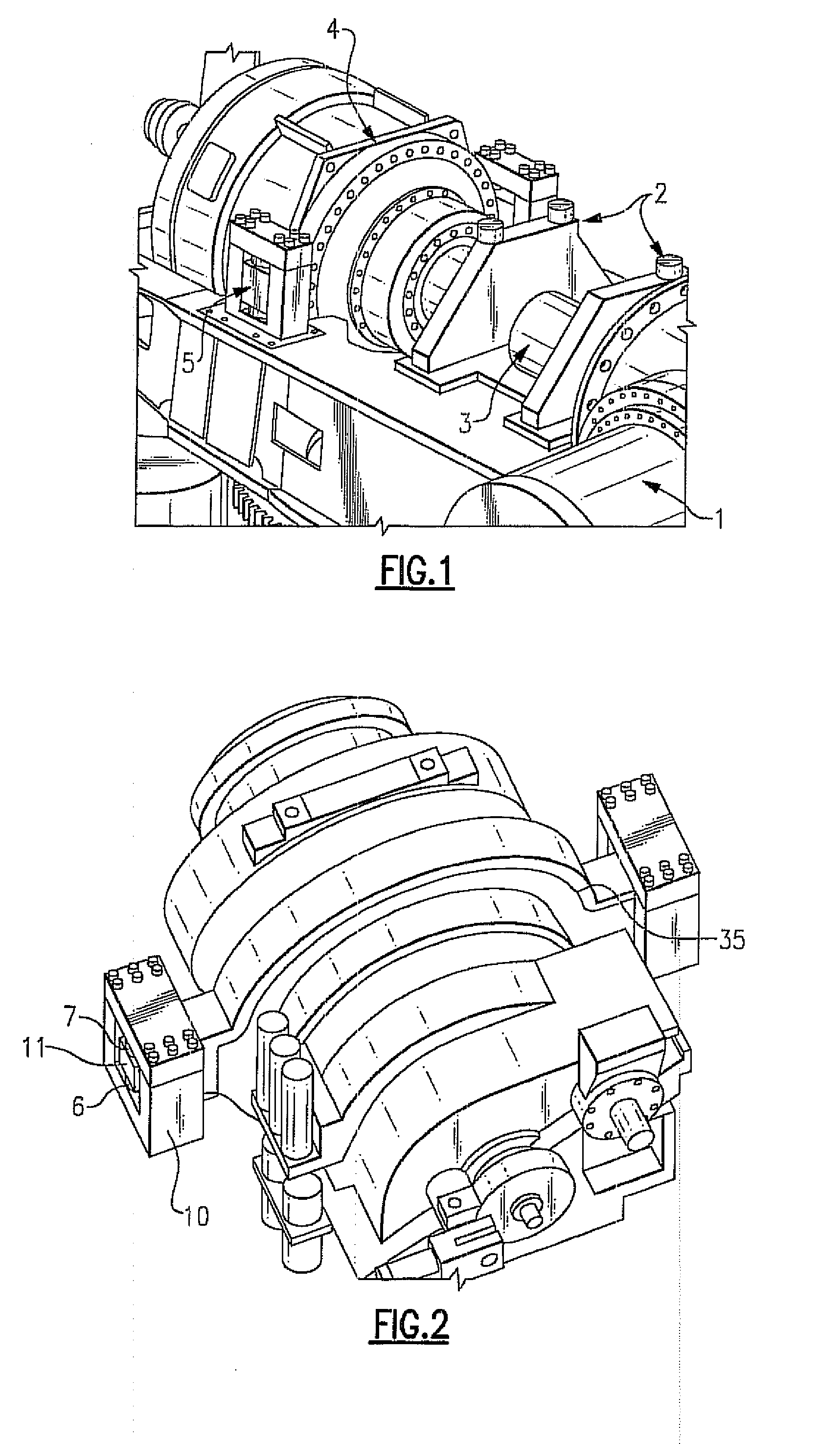
system is the indeterminate support resulting from four bearing points.
This indeterminate support gives rise to constraining forces which may have the following causes: manufacturing and assembly tolerances, misalignment, inclination at the rotor shaft and at the gearbox flange and not least bending of all load-bearing elements relative to one another in the event of unsymmetrically acting force transmission by the rotor.
These are caused, for example, by uneven wind interference suppression or by the rotor blade moving past the tower.
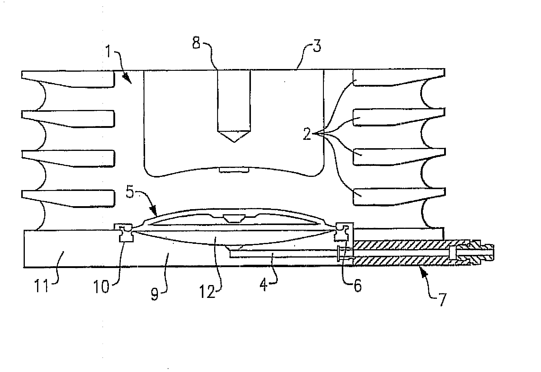
However, this also causes a large rotary movement of the gearbox on load transmission, which in turn causes a displacement of the gearbox output shaft relative to the generator shaft, which is disadvantageous, and consequently this softness of the elastomer components can only be used to a limited extent, or accordingly complex couplings are required between gearbox and generator.
In practice, these spring elements, although achieving the desired technical effects in respect of the damping, have proved to be problematical since, under the requisite high pressures that have to be generated in order to increase the stiffness in the vertical direction sufficiently, leak-tightness problems repeatedly occur, with loss of hydraulic fluid, even though the elastomer layers compressed by hydraulic fluid are firmly connected to the surrounding parts by vulcanization and / or adhesive bonding.
After further investigations and tests with the spring element described in EP 1 566 543, but also generally in other elastomer bearing arrangements of the prior art, it has now been found, surprisingly, that large-volume elastomer components in particular cannot be readily sealed when they are in contact with hydraulic fluids of whatever type (e.g. water, oil, alcohols, mixtures of the same) under pressure.
Small droplets of the hydraulic fluid are apparently absorbed, on continuous loading and under higher pressures, by the porous structure present, particularly in the case of large elastomer volumes, and are continuously transported further by the flow structures which are difficult to avoid in the elastomer material, until they escape at various, often unexpected, points of the component.
Without wishing to be tied to a theory, these results may be interpreted in such a way that a droplet of the hydraulic fluid in the corresponding hydraulic space is forced into a small notch or pore in the surface of the adjacent elastomer which opens and closes during the dynamic loading, so that the droplet is locked in and continuously conveyed further until it reaches the end of the elastomer or component and thus results in a leak.
The escape of hydraulic fluid from the spring elements or bearings of EP 1 566 543 A1 thus represents a serious problem which has to be solved.
Moreover, it has been found that direct contact of the hydraulic fluid with the elastomer material of the spring elements may lead to reduced durability or elasticity of the elastomer under the influence of high pressures, meaning that the corresponding spring elements may have to be replaced earlier.

Method used


Image

  • Hydraulically prestressed elastomer spring element and the use thereof in wind turbine bearings
  • Hydraulically prestressed elastomer spring element and the use thereof in wind turbine bearings
  • Hydraulically prestressed elastomer spring element and the use thereof in wind turbine bearings

Examples


Embodiment Construction

[0040]The elastomeric materials used for the layers (1) according to the invention consist essentially of a natural rubber, a natural rubber derivative or of a suitable elastic polymeric plastic or plastic mixture. The elastomer layer can, in accordance with the invention, have different hardness (“Shore hardness”) and different damping properties, according to the desired requirements. Elastomers having a Shore A hardness of 20 to 100, in particular 30 to 80, are preferably used. The production of such elastomers of different hardness is known in the prior art and adequately described in the relevant literature.

[0041]The non-elastomeric intermediate plates or intermediate layers (2) are, in accordance with the invention, as far as possible made from nonelastic materials of low compressibility. These are preferably metal plates, but other materials, such as hard plastics, composite materials or carbon-fiber-containing materials, can also be used. The intermediate plates and the elas...


PUM


Abstract

The invention relates to spring elements and bearings which contain these spring elements, the spring stiffness of the bearings and spring elements being individually adjustable by deformable elastomer bodies or elastomer layers by prestressing. The deformation of the elastomer layers and hence of the spring elements is achieved by an appropriately designed hydraulic device. The leak-tightness of the spring elements and bearing elements according to the invention is achieved through special hydraulically prestressed sealing elements, use of a pressure membrane and special structural features of the elastomer elements.

Description

[0001]This application claims priority from EP Application Serial No. EP 07 01 1 643.9 filed Jun. 14, 2007.FIELD OF THE INVENTION[0002]The invention relates to spring elements and bearings which contain these spring elements, the spring stiffness of the bearings and spring elements being individually adjustable by deformable elastomer bodies or elastomer layers by prestressing. The deformation of the elastomer layers and hence of the spring elements is achieved by an appropriately designed hydraulic device. The leak-tightness of the spring elements and bearing elements according to the invention is achieved through special hydraulically prestressed sealing elements, use of a pressure membrane and special structural features of the elastomer elements. The elastomer bearing arrangements according to the invention, including their spring elements, are suitable, in particular, for use in two- or multi-point bearing arrangements in rotor constructions and gearbox constructions of large w...

Claims


Application Information

Patent Timeline
Patent Type & Authority Applications(United States)
IPC IPC(8): F16C35/00F16F7/12
CPCF16F1/40F16F2228/08F16F13/08F03D80/70F05B2240/50
Inventor MITSCH, FRANZ
Owner FM ENERGIE GMBH& CO KG
Why Eureka
Try Eureka