Eureka AIR delivers breakthrough ideas for toughest innovation challenges, trusted by R&D personnel around the world.

Dust Sealing

Inactive Publication Date: 2008-12-18
SANDVIK INTELLECTUAL PROPERTY AB
View PDF3 Cites 2 Cited by
  • Summary
  • Abstract
  • Description
  • Claims
  • Application Information

AI Technical Summary

Benefits of technology

[0007]One object of the present invention is to have a dust sealing in the form of a module system, for easy handling. No welding is used and no metal parts. The weight is kept low by not using metals. A further object is to control flexing of the sealing strip. According to the invention, this is done in that the sealing strip, is arranged slanted in relation to the sides of the vibrating screen and stationary cover, respectively.

Problems solved by technology

In the crushers, screens and in the transports in and out of the different machines, there is often a relatively extensive dust formation.
As the sealing strip is flexing in several directions, it is likely to rupture after a relatively short time, due to the flexing back and forward.
However at start and especially at stop, the vibrating screen may move considerably more, due to natural oscillation.

Method used


Image

  • Dust Sealing
  • Dust Sealing
  • Dust Sealing

Examples


Embodiment Construction

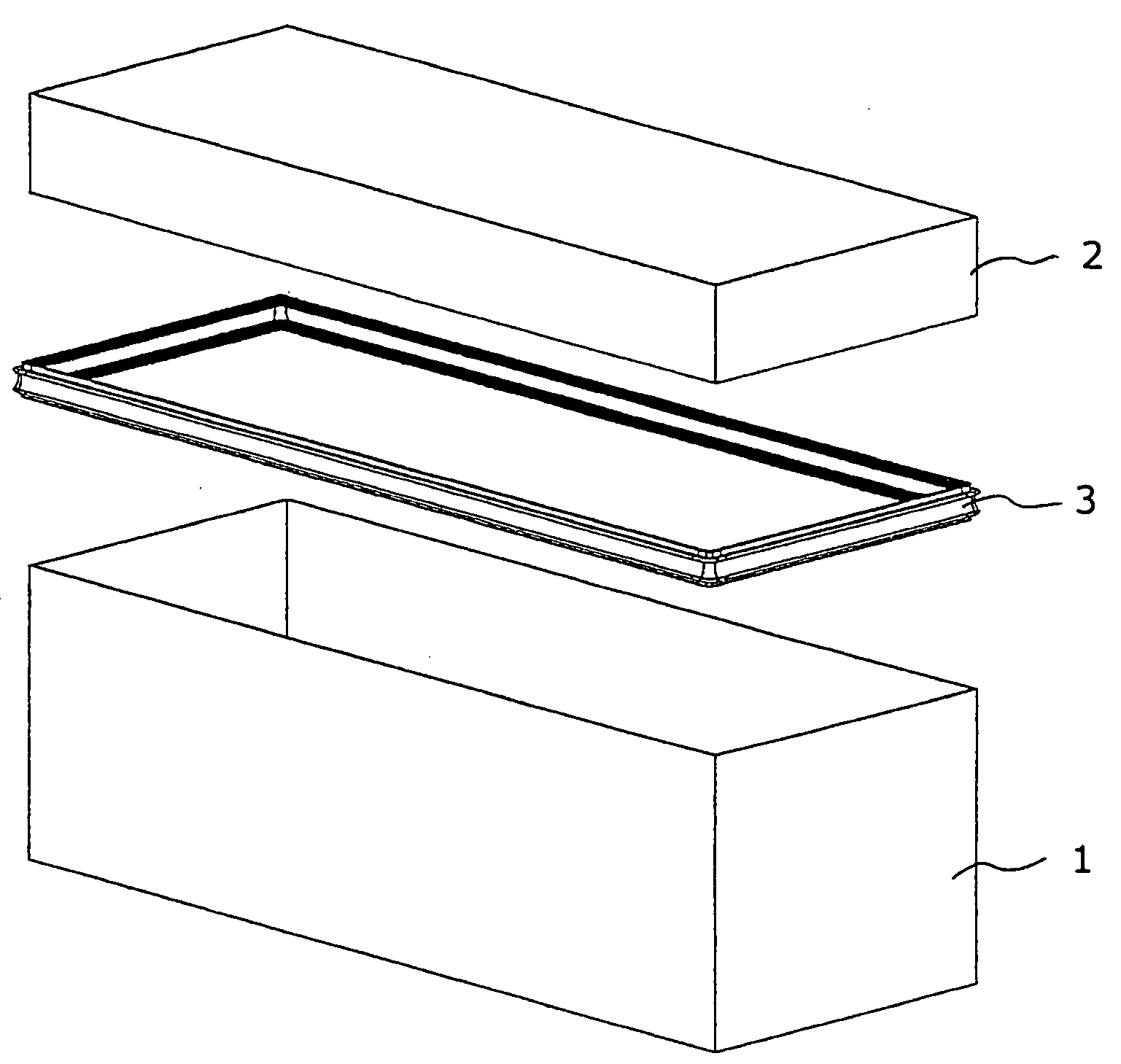
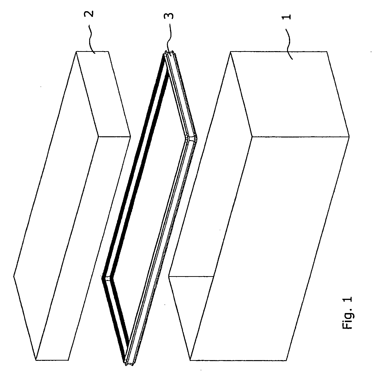
[0016]In FIG. 1, a vibrating screen 1, a stationary cover 2 and a sealing strip 3 are shown schematically. The sealing strip 3 is to be placed between the vibrating screen 1 and the stationary cover 2 to seal against dust leaving the vibrating screen 1. Normally, the stationary cover 2 has an opening through which the gravel etc. is fed to the vibrating screen 1 or feeder.

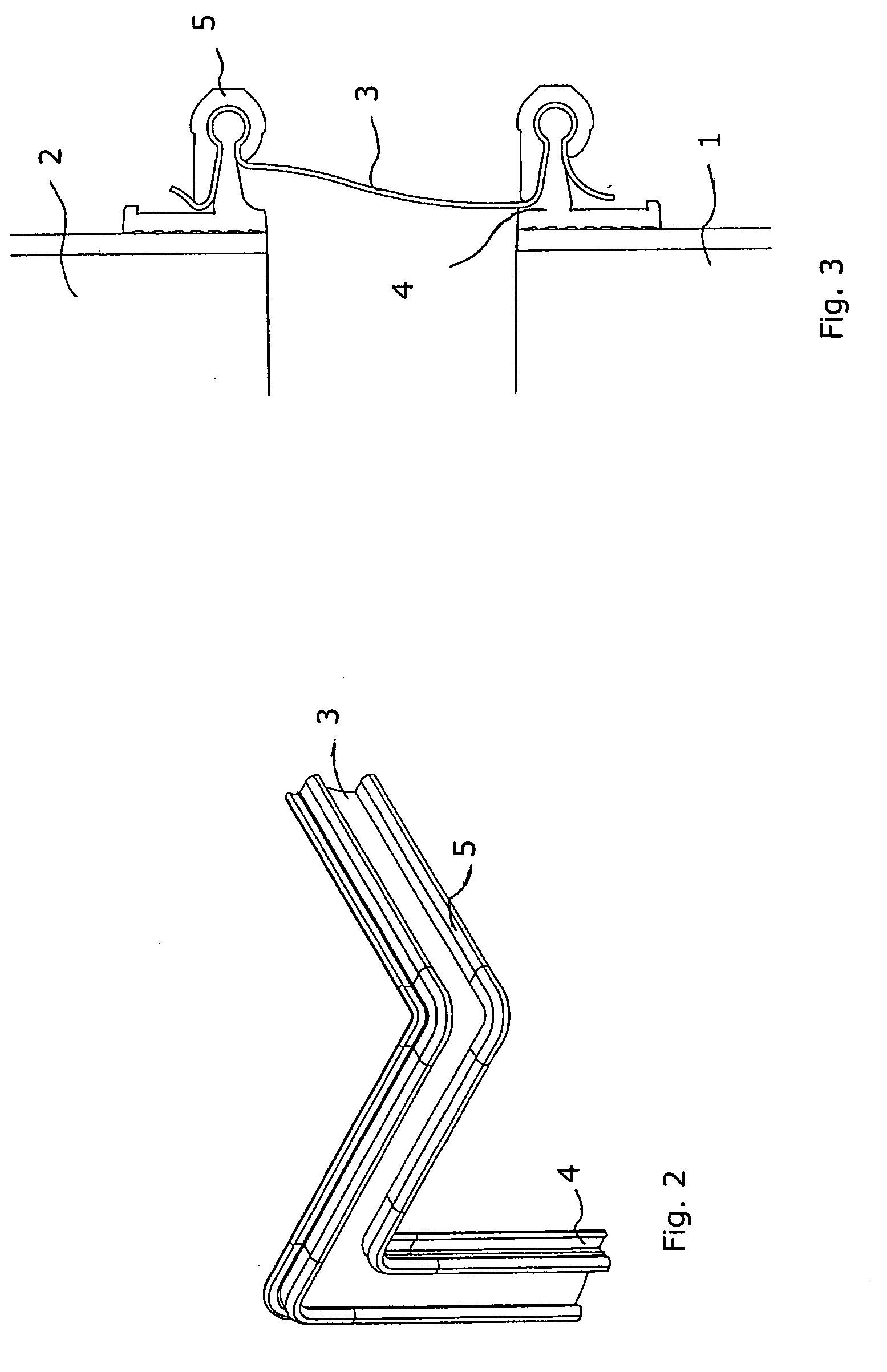
[0017]To attach the sealing strip 3 to the vibrating screen 1 and the stationary cover 2, respectively, snap profiles 4 are fixed on both the vibrating screen 1 and the stationary cover 2. The sealing strip 3 is then mounted to the snap profiles 4 by way of grip strips 5.

[0018]The snap profiles 4 are fixed close to the edges of the vibrating screen 1 and stationary cover 2, respectively. The snap profiles 4 have a base 8, a rib 6 extending at right angles from the base 8, and a bar 7 placed on top of the rib 6. The snap profiles 4 are placed all around the vibrating screen 1 and stationary cover 2, respectively.

[00...


PUM


Abstract

The present invention concerns a system for sealing between a rock processing equipment, such as a vibrating screen and a stationary cover or other part. A sealing strip is arranged between the vibrating screen and the stationary cover. The sealing strip is attached to snap profiles fixed to the vibrating screen and the stationary cover, respectively. The sealing strip is fixed to the snap profiles by means of grip strips. The sealing strip is placed slanted in relation to the sides of the vibrating screen and stationary cover, respectively.

Description

CROSS-REFERENCE TO PRIOR APPLICATION[0001]This application claims priority to Swedish Application No. 0701480-6 filed Jun. 15, 2007, which is incorporated by reference herein.FIELD OF THE INVENTION[0002]The present invention concerns dust sealing between a rock processing equipment, such as a vibrating screen, feeder, hopper, chute, crusher or the like, and a cover or other part.BACKGROUND OF THE INVENTION[0003]As used in this description the terms “upper”, “lower” and similar expressions are in relation to the directions as shown in the drawings.[0004]In rock processing systems, rocks and large stones are first fed to a crusher and then the crushed material is transported to a vibrating screen or the like. In the crushers, screens and in the transports in and out of the different machines, there is often a relatively extensive dust formation. There is a general ambition to encapsulate the dust in and between the different machines and transport devices. In order to have dust encaps...

Claims


Application Information

Patent Timeline
IPC IPC(8): F16J15/02
CPCF16J3/02F16J15/52F16J15/061F16J15/00
Inventor MALMBERG, MATS
Owner SANDVIK INTELLECTUAL PROPERTY AB
Why Eureka
Eureka Blog
Learn More