Modular blade enclosure power subsystem disign

Inactive Publication Date: 2008-12-18
HEWLETT PACKARD DEV CO LP
View PDF43 Cites 13 Cited by
  • Summary
  • Abstract
  • Description
  • Claims
  • Application Information

AI Technical Summary

Problems solved by technology

The power subsystem, however, is generally a fixed power supply ...

Method used


Image

  • Modular blade enclosure power subsystem disign
  • Modular blade enclosure power subsystem disign
  • Modular blade enclosure power subsystem disign

Examples


Embodiment Construction

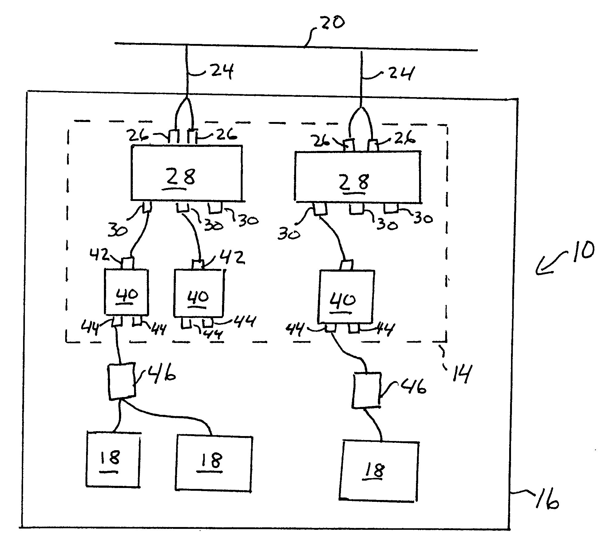
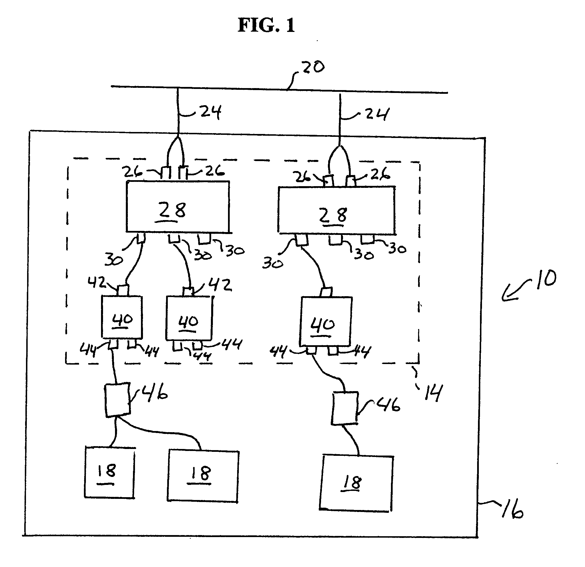
[0019]The present inventors have realized that it can be costly to have different dedicated enclosure designs to support all the different types of facilities power environments. Further, in the case of a server computer system, it is very desirable to have the power subsystem reside within the same enclosure as the computing modules of the server, such as the server blades, switches, fans, and enclosure management modules, as compared to external solutions, where the power subsystem is not within the same enclosure. Thus, the present inventors have contemplated a modularized power subsystem design, with removable power input modules and power conversion modules, such as hot plug power supplies. Such a modular design provides tremendous flexibility at minimal cost. The modularized approach overcomes problems with prior power subsystem solutions which have generally been fixed power supply systems that only offer a customer one choice of power access per unit.

[0020]For facilities wit...


PUM


Abstract

An apparatus for distributing power to computing modules in a multi module enclosure. The apparatus includes at least one power input module, a plurality of power input cables, a plurality of power conversion modules, and a plurality of computing modules. The at least one power input module is modularly arranged within the multi module enclosure. The plurality of power input cables are electrically connected to and provide power input to the at least one power input module. The plurality of power conversion modules are electrically connected to power outputs of the at least one power input module and are modularly arranged within the multi module enclosure. The plurality of computing modules are electrically connected to power outputs of the power conversion modules and are arranged within the multi module enclosure.

Description

CROSS-REFERENCE TO RELATED PATENT APPLICATIONS[0001]This application claims priority from Provisional Application U.S. Application 60 / 943,973, filed Jun. 14, 2007, incorporated herein by reference in its entirety.BACKGROUND OF THE INVENTION[0002]The present invention relates generally to the field of enclosure power subsystems.[0003]A server typically comprises a number of modules, such as server blade, switch, fan and enclosure management modules. These modules require power, which is supplied from a power subsystem, which converts power from facility power where the server modules are disposed, to the modules. The power subsystem typically comprises a power input module, which is electrically connected to the AC power of the facility in the 100V to 250 V range. The power input module provides AC power to one or more power conversion modules, which convert the AC power to DC power to be provided to power using modules, such as server blade, switch, fan and enclosure management modu...

Claims


Application Information

Patent Timeline
IPC IPC(8): H02J3/00H02J1/00
CPCH01R31/02H01R2201/06H05K7/1492
Inventor GIBSON, GREGORY L.SHERROD, DAVID W.JAMESOU, JONATHAN E.STEPHENSON, SCOTT
Owner HEWLETT PACKARD DEV CO LP
Why Eureka
Try Eureka