

Magnetic particle imaging apparatus, method of disposing detection coil for magnetic particle imaging apparatus, and magnetic flux detecting apparatus
- Summary
- Abstract
- Description
- Claims
- Application Information
AI Technical Summary
Benefits of technology
Problems solved by technology
Method used
Image

Examples
first embodiment
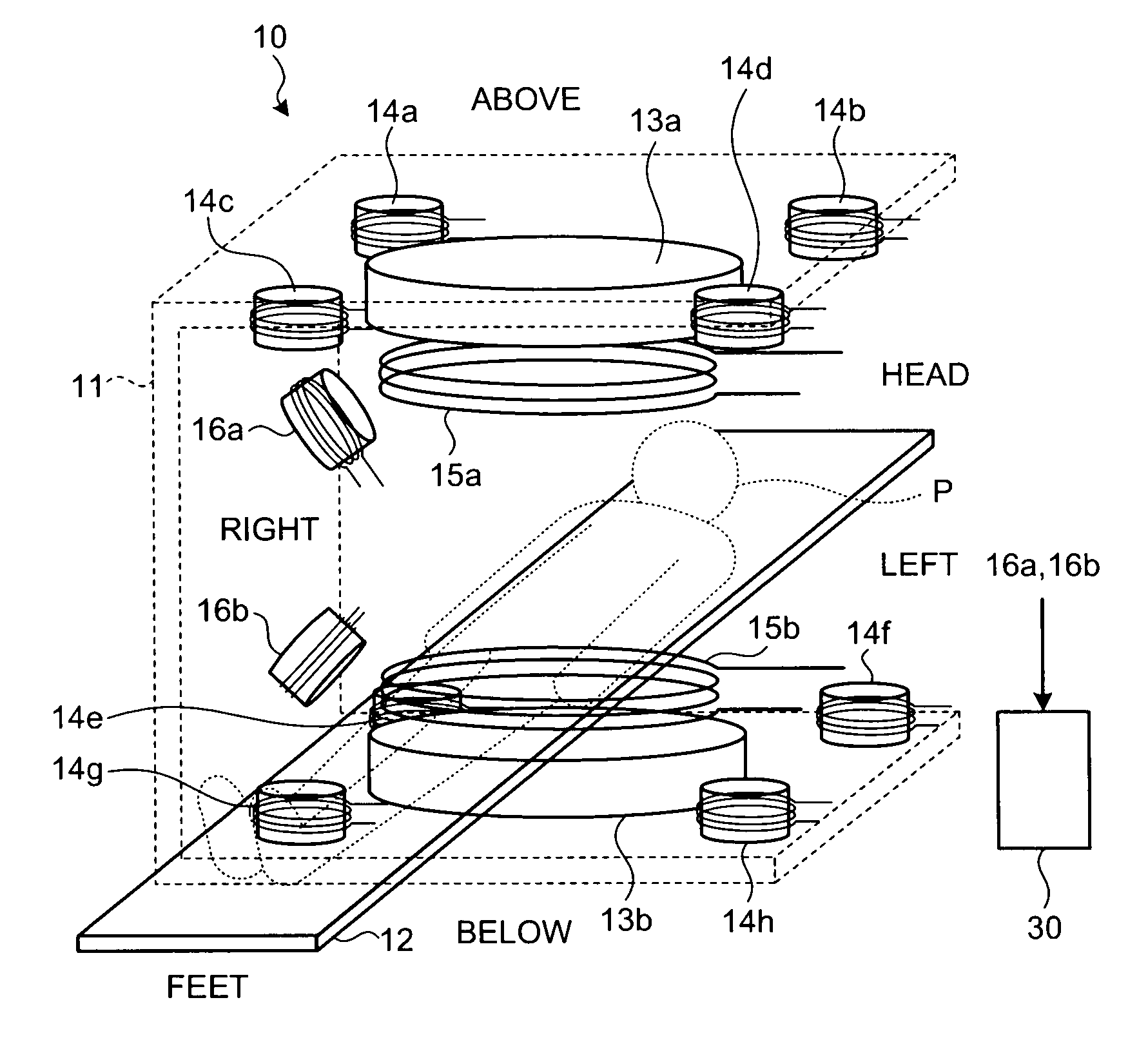
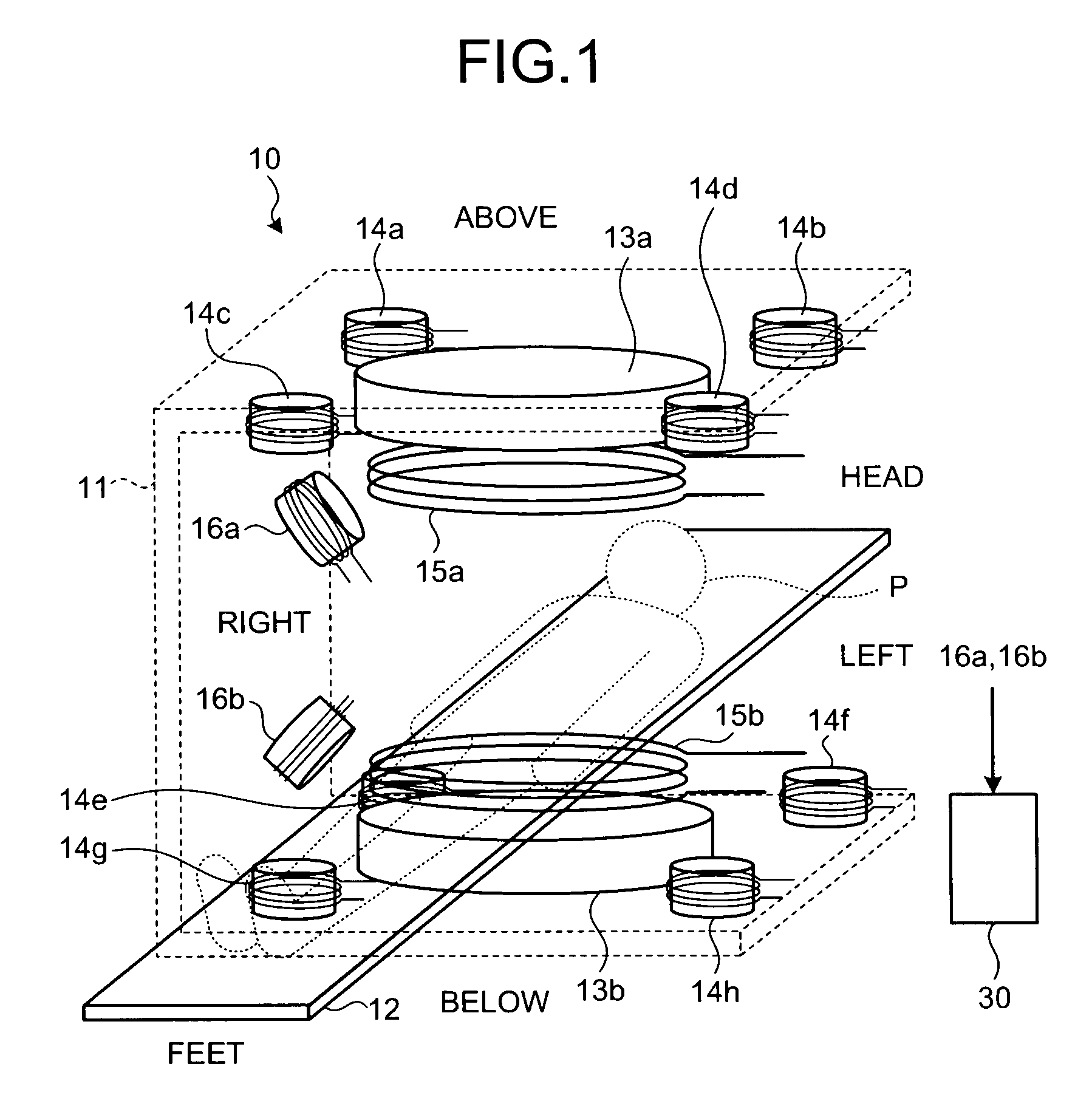
[0035]FIG. 1 is a perspective view of a configuration of a magnetic particle imaging apparatus according to a As shown in FIG. 1, a magnetic particle imaging apparatus 10 includes a frame 11, a top plate 12, permanent magnets 13a and 13b, zero magnetic-field scan coils 14a to 14h, modulation coils 15a and 15b, detection coils 16a and 16b, and an image processing unit 30.
[0036]The frame 11 is a u-shaped component and supports the permanent magnets 13a and 13b, the zero magnetic-field scan coils 14a to 14h, the modulation coils 15a and 15b, and the detection coils 16a and 16b.
[0037]The top plate 12 is a plate-shaped component provided in an approximate center of an area surrounded by the frame 11. A subject P (such as a patient) to be imaged is placed on the top plate 12. The top plate 12 is moved by an apparatus (not shown). Here, directions above and below, right and left, and head and feet are defined based on the subject P placed on the top plate 12 on his back.
[0038]The permane...
second embodiment
[0083]Therefore, following configuration and method are described. In the configuration and method, a feedback coil is provided for adjusting a balance in the modulation magnetic field applied by the modulation coils 15a and 15b. The feedback coil is driven based on a result actually detected by the detection coil. As a result, the magnetic field interlinked with the detection coil and generated by the modulation coils 15a and 15b is made completely zero. Here, for convenience of explanation, functional sections achieving same purposes as each section in FIG. 1 are given the same reference numbers. Detailed explanations thereof are omitted.
[0084]FIG. 13 is a diagram for explaining control of the feedback coil according to the second embodiment. Four serially connected detection coils 16k to 16n are disposed, in which two detection coils 16k and 16l on the inner side of the modulation coil 15a and two detection coils 16m and 16n on the outer side of the modulation coil 15b. A feedba...
PUM
 Abstract
Description
Claims
Application Information