Single band antenna

a single-band antenna and antenna earthing technology, applied in the field of single-band antennas, can solve the problems of limiting the design and arrangement of single-band antennas, not meeting the demand for miniaturization, and the inability of the radio transmission system to transmit and receive data, etc., to achieve the same resonance length, short profile, and easy miniaturization

Inactive Publication Date: 2008-12-18
ARCADYAN
View PDF0 Cites 2 Cited by
  • Summary
  • Abstract
  • Description
  • Claims
  • Application Information

AI Technical Summary

Benefits of technology

[0011]As mentioned above, the radiating unit of the single band antenna of the invention has a bent portion. Compared with the prior art, the radiating unit can achieve the same resonance length with a shorter profile, so that the single band antenna can be more easily miniaturized. In addition, it is testified and verified that the inductance-capacitance effect of the single band antenna of the invention can be greatly enhanced through the bent portion of the radiating unit. That is, the distance between the feeding unit and the grounding unit in the invention can be less than that in the prior art. It hence reduces the design limitations and increases the adaptability and efficiency of the antenna. In addition, the grounding unit and feeding unit of the single band antenna of the invention can be connected to the circuit board by surface mounting technology (SMT), hence simplifying the manufacturing process and enhancing the structure strength.

Problems solved by technology

Without an antenna, the radio transmission system cannot transmit and receive data.
Unfortunately, this feature also restricts the design and arrangement of the single band antenna 1.
Furthermore, since the radiating unit 11 of the single band antenna 1 has a stripe shape, it can not accommodate the demand for miniaturization when the single band antenna 1 is too long, especially when it operates in a low frequency (LF) band.

Method used


Image

  • Single band antenna
  • Single band antenna
  • Single band antenna

Examples


Embodiment Construction

[0022]The present invention will be apparent from the following detailed description, which proceeds with reference to the accompanying drawings, wherein the same references relate to the same elements.

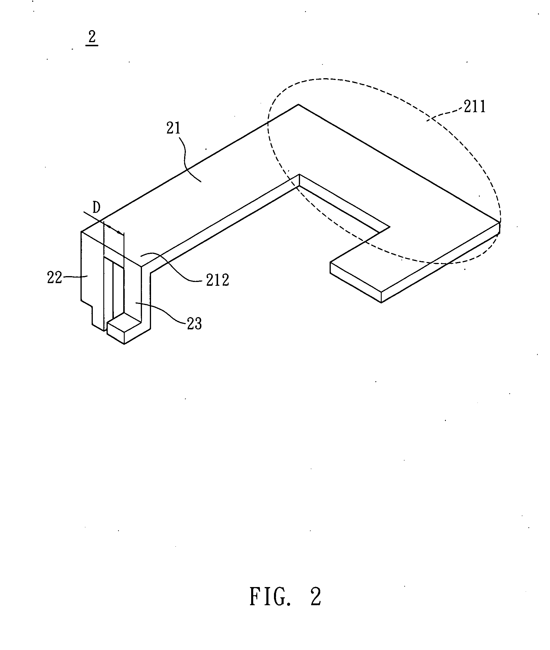
[0023]As shown in FIG. 2, a single band antenna 2 according to a preferred embodiment of the invention includes a radiating unit 21, a grounding unit 22 and a feeding unit 23. The radiating unit 21 has a bent portion 211. In the embodiment, the radiating unit 21 is a metal plate, and the bent portion 211 may have a right angle or may be hook-shaped or arc-shaped. The grounding unit 22 and the feeding unit 23 protrude from one end 212 of the radiating unit 21, and an interval, distance D, is provided between the grounding unit 22 and the feeding unit 23. In the embodiment, the distance D is smaller than 3 mm.

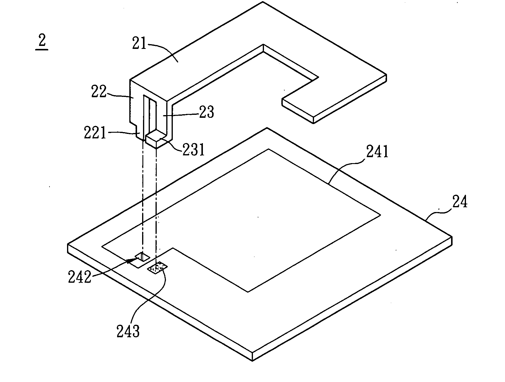
[0024]As shown in FIG. 3, the single band antenna 2 further includes a substrate 24. The radiating unit 21 is disposed on the substrate 24 by the grounding unit 22 and the feeding ...


PUM


Abstract

A single band antenna includes a radiating unit, a grounding unit, a feeding unit and a conductive unit. The radiating unit has a bent portion. The grounding unit and the feeding unit protrude from one end of the radiating unit with an interval therebetween. The conductive unit has a conductive body and a grounding body. The conductive body is electrically connected with the feeding unit, and the grounding body is electrically connected with the grounding unit.

Description

BACKGROUND OF THE INVENTION[0001]1. Field of Invention[0002]The invention relates to an antenna and, in particular, to a single band antenna.[0003]2. Related Art[0004]The rapid developments in radio transmission have brought various products and technologies to market, particularly in the field of multi-band transmission, in order for products to meet the consumer's ever developing requirements. The antenna is an important element for transmitting and receiving electromagnetic wave energy in radio transmission systems. Without an antenna, the radio transmission system cannot transmit and receive data. Thus, the antenna plays an indispensable role in the radio transmission system.[0005]An appropriate antenna is selected to accommodate product features and enhance the transmission while minimizing product cost. Different methods and different materials for manufacturing the antennas are used in different products. In addition, antennas are designed in consideration of different freque...

Claims


Application Information

Patent Timeline
Patent Type & Authority Applications(United States)
IPC IPC(8): H01Q9/06
CPCH01Q9/0421H01Q9/42
Inventor TAO, WEN-SZU
Owner ARCADYAN
Why Eureka
Try Eureka