Systems and Methods for Displaying Three-Dimensional Images

a technology of three-dimensional images and systems, applied in the field of systems and methods for displaying three-dimensional (3d) images, can solve the problems of reducing spatial resolution, requiring viewers to wear glasses, and appearing less realistic to a viewer

Inactive Publication Date: 2008-12-18
THE TRUSTEES OF COLUMBIA UNIV IN THE CITY OF NEW YORK
View PDF99 Cites 31 Cited by
  • Summary
  • Abstract
  • Description
  • Claims
  • Application Information

AI Technical Summary

Benefits of technology

[0010]Various embodiments of the present invention provide 3D display systems and methods that overcome various shortcomings discussed above. For instance, the 3D display systems of various of embodiments of the present invention do not require the use of specialized glasses or a large amount of light power. Moreover, the 3D display systems of various of embodiments of the present invention can provide different perspectives of a displayed 3D scene to viewers located at different viewing angles and / or not show points that should be hidden from viewers.

Problems solved by technology

Because 2D images do not contain depth information, they appear to be less realistic to a viewer.
However, this approach suffers from the drawback that viewers must wear glasses in order to have a 3D experience.
However, this approach suffers from the drawback that spatial resolution is significantly reduced.
In this case, an enormous amount of light energy is needed for the scene to appear crisp and bright.
As a result, it is difficult to scale such an approach to cover reasonably large display spaces.
Finally, this approach is limited because it does not adequately handle points that are hidden from the viewer.
This approach also suffers from the drawback that an enormous amount of light energy is required to create a bright 3D scene.
Such displays do not create a four-dimensional light field because the directional radiance of each point cannot be controlled.
Unfortunately, conventional holographic displays can only display low quality images.

Method used


Image

  • Systems and Methods for Displaying Three-Dimensional Images
  • Systems and Methods for Displaying Three-Dimensional Images
  • Systems and Methods for Displaying Three-Dimensional Images

Examples


Embodiment Construction

including the description of various embodiments of the invention will be best understood when read in reference to the accompanying figures wherein:

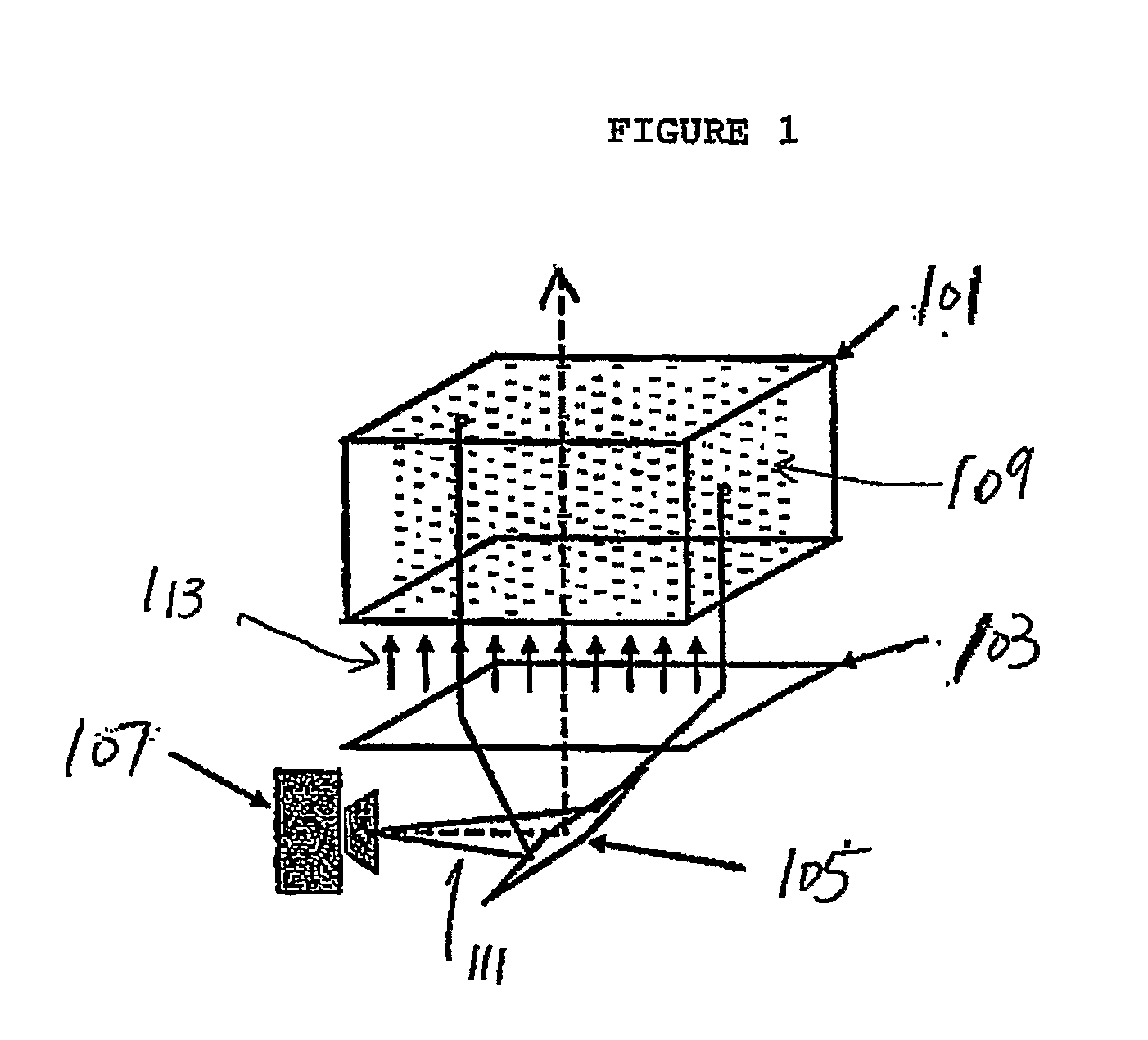
[0016]FIG. 1 is a perspective view illustrating a volumetric display system using passive optical elements according to various embodiments of the present invention;

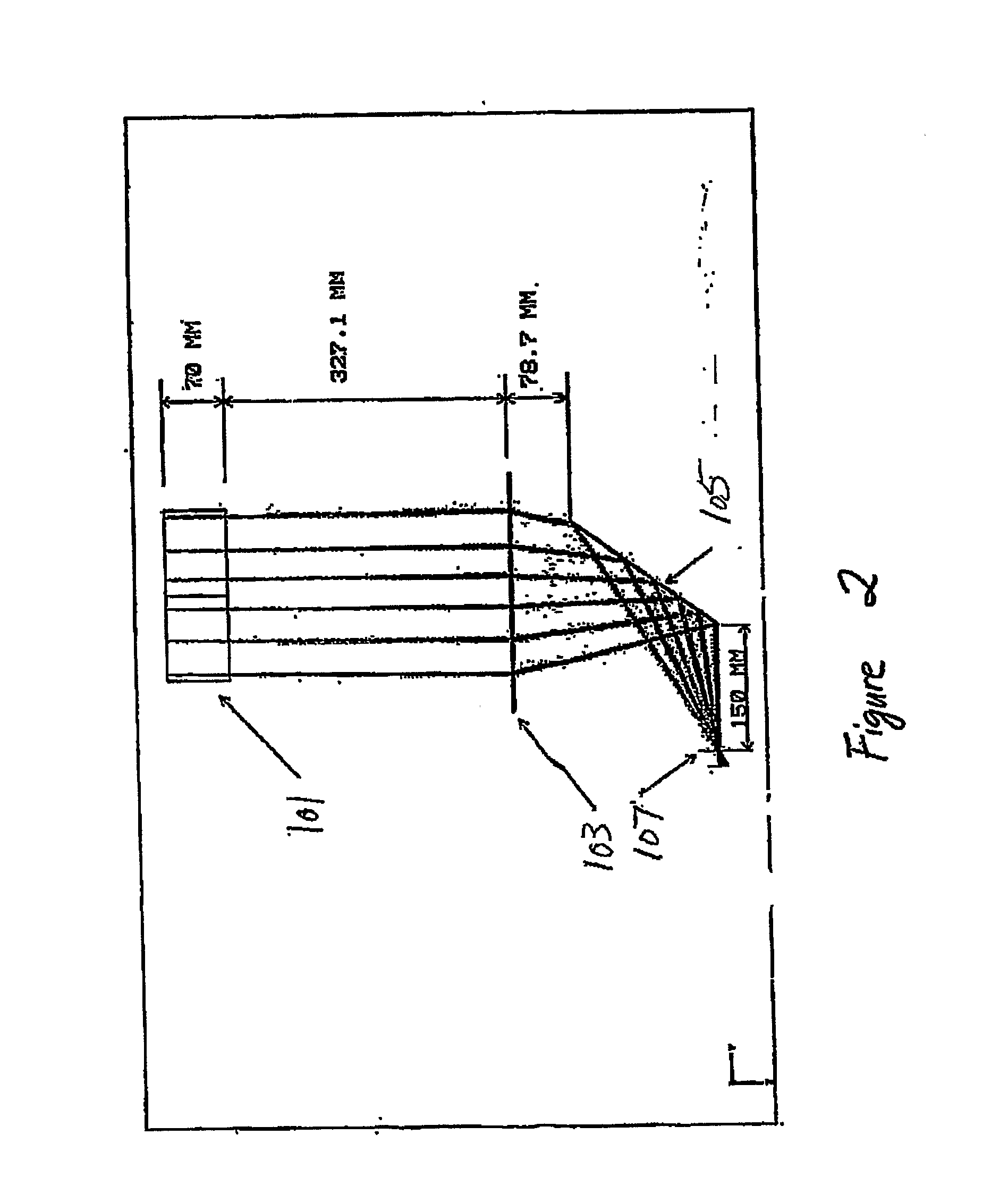
[0017]FIG. 2 is a cross-sectional view of a volumetric display system illustrated in FIG. 1;

[0018]FIG. 3 a cross-sectional view of another volumetric display system according to various embodiments of the present invention;

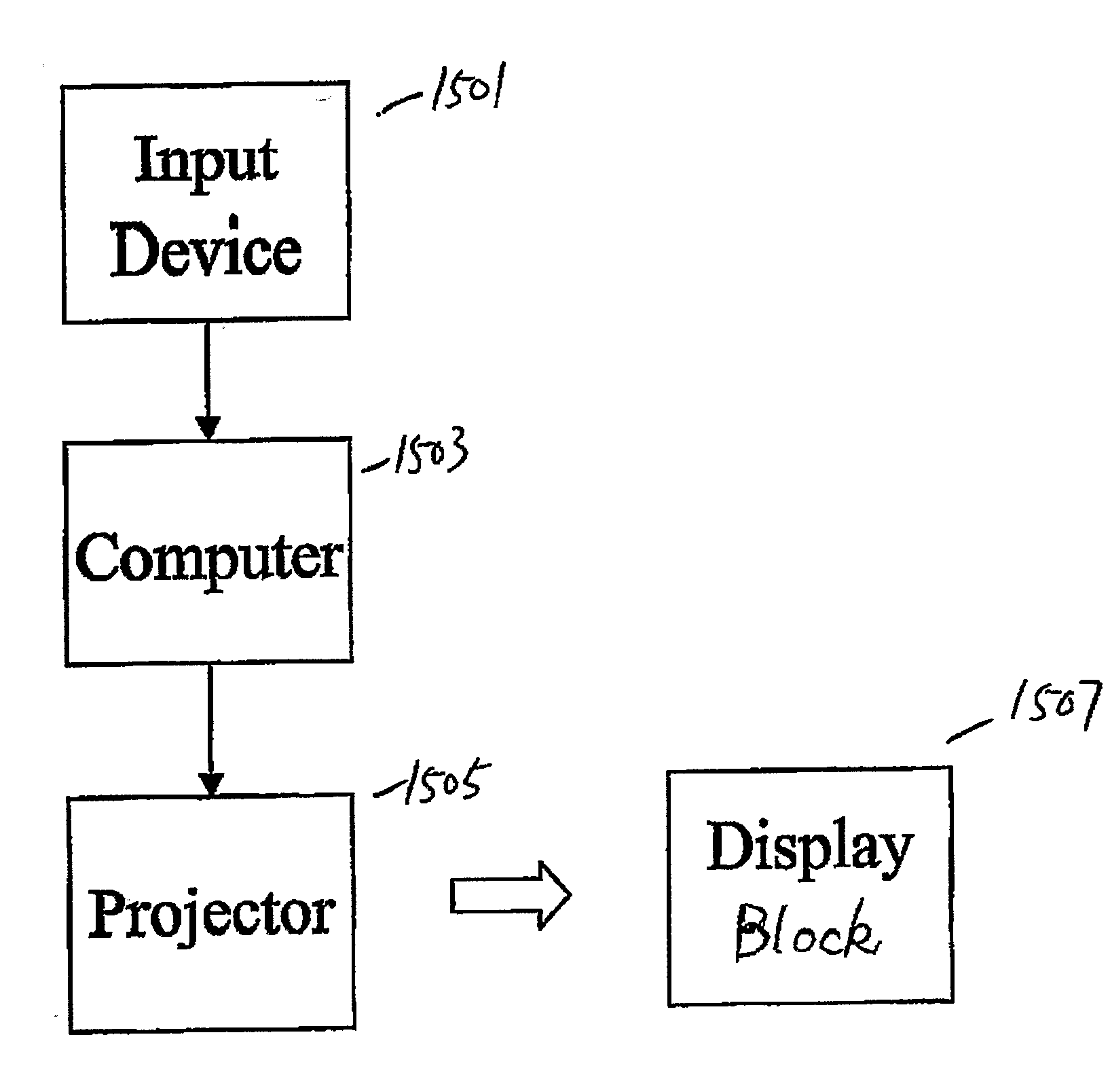
[0019]FIG. 4 is a diagram illustrating an example of a volumetric display system according to various embodiments of the present invention;

[0020]FIG. 5 is a diagram illustrating a relationship between passive optical elements and projector pixels in an example of a volumetric display system according to various embodiments of the present invention;

[0021]FIG. 6 is a flow chart illustrating the steps for displaying 3D images using a volumetric display system...


PUM


Abstract

Systems and methods for displaying three-dimensional (3D) images are described. In particular, the systems can include a display block made from a transparent material with optical elements three-dimensional disposed therein. Each optical element becomes luminous when illuminated by a light ray. The systems can also include a computing device configured to generate two-dimensional (2D) images formatted to create 3D images when projected on the display block, by a video projector coupled to the computing device. The video projector is configured to project the 2D images on the block to create the 3D images by causing a set of the passive optical elements to become luminous. Various other systems and methods are described for displaying 3D images.

Description

RELATED APPLICATIONS[0001]This application claims the priority of U.S. Provisional Patent Application No. 60 / 621,837, filed on Oct. 25, 2004; U.S. Provisional Patent Application No. 60 / 651,740, filed on Feb. 10, 2005; and U.S. Provisional Patent Application No. 60 / 726,301, entitled “Systems and Methods for Producing Three-Dimensional Displays,” filed on Oct. 12, 2005, which are incorporated herein by reference in their entirety.FIELD OF THE INVENTION[0002]The present invention relates to systems and methods for displaying three-dimensional (3D) images. More particularly, the present invention relates to systems and methods for displaying 3D images using passive optical elements in a display block. The present invention also relates to systems and methods for displaying 3D images using anamorphic light engines and / or reflective elements having curved surfaces.BACKGROUND OF THE INVENTION[0003]Systems for displaying images (for both static and video images) have become a ubiquitous par...

Claims


Application Information

Patent Timeline
Patent Type & Authority Applications(United States)
IPC IPC(8): H04N9/31H04N13/395H04N13/363
CPCH04N13/0242H04N13/0404H04N13/0409H04N13/0427H04N13/0447H04N13/0459H04N13/0488H04N13/0495H04N13/305H04N13/395H04N13/243H04N13/388H04N13/31H04N13/363H04N13/365H04N13/351
Inventor NAYAR, SHREE K.
Owner THE TRUSTEES OF COLUMBIA UNIV IN THE CITY OF NEW YORK
Why Eureka
Try Eureka