Metallic cover and method for making the same

a metal cover and metal drawing technology, applied in the field of metal covers, can solve the problems of reducing the quality of the metallic cover, the inability to make the sharp corner edge by metal drawing method, and the inability to achieve the sharp corner edg

Active Publication Date: 2008-12-18
CLOUD NETWORK TECH SINGAPORE PTE LTD +1
View PDF1 Cites 11 Cited by
  • Summary
  • Abstract
  • Description
  • Claims
  • Application Information

AI Technical Summary

Benefits of technology

[0009]In one aspect, a metallic cover includes a bottom base and a plurality of side walls. The side walls extend from bottom base. The bottom base and each of the side walls cooperatively are connected by an edge structure. The metallic cover is made of a metallic material that has a yield strength in the range from about 80 MPa to about 150 MPa, an elongation ratio in the range from about 15% to about 28%, and a hardness in the range from about 45 HV0.2 to about 70 HV0.2.

Problems solved by technology

Generally, the sharp-cornered edge is impossible to be made by metal drawing method.
However, the above described method is prone to cause cracks in the edge structure of the metallic cover, thus decreasing quality of the metallic covers.
After the anodizing process, color of surface of the edge structure of the metallic cover is quite different from that of other parts of the metallic cover, thereby decreasing the quality of the appearance of the cover.

Method used


Image

  • Metallic cover and method for making the same
  • Metallic cover and method for making the same
  • Metallic cover and method for making the same

Examples


Embodiment Construction

[0020]Reference will now be made to the drawings to describe preferred embodiments of the present metallic cover and method in detail.

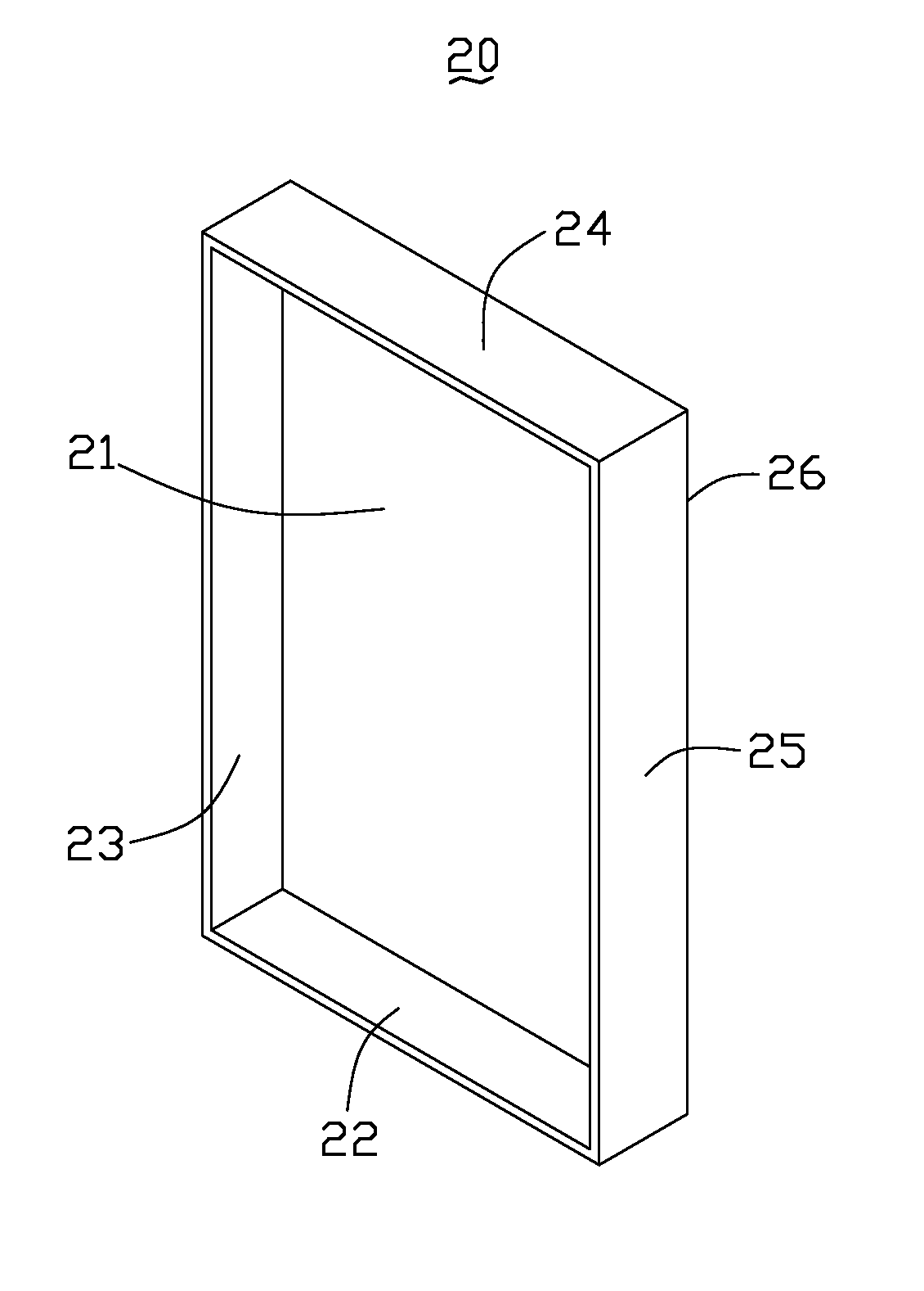
[0021]Referring to FIG. 1, a metallic cover 20 according to one embodiment is shown. In the illustrated embodiment, the metallic cover 20 is used as a cover for a flat-panel display device. The metallic cover 20 includes a rectangular bottom base 21, a first side wall 22, a second side wall 23, a third side wall 24, and a fourth side wall 25. The side walls 22, 23, 24, 25 perpendicularly extend from a periphery of the rectangular bottom base 21. The side walls 22, 23, 24, 25 cooperatively define a cavity (not labeled). The bottom base 21 and each of the side walls 22, 23, 24, 25 are correspondingly connected by an edge structure 26. The edge structure 26 is a sharp-cornered edge. The angle formed between an outer surface 261 (see FIG. 6) of the bottom base 21 and the outer surface 261 of each of the sidewalls 22, 23, 24, 25 at the edge structure 26 is...


PUM

PropertyMeasurementUnit
elongation ratioaaaaaaaaaa
yield strengthaaaaaaaaaa
elongation ratioaaaaaaaaaa

Abstract

An exemplary metallic cover (20) includes a bottom base (21) and a plurality of side walls (22, 23, 24, 25). The side walls extend from bottom base. The bottom base and each of the side walls are connected by an edge structure (26). The metallic cover is made of a metallic material that has a yield strength in the range from about 80 MPa to about 150 MPa, an elongation ratio in the range from about 15% to about 28%, and a hardness in the range from about 45 HV0.2 to about 70 HV0.2. A method for making the metallic cover is also provided.

Description

BACKGROUND OF THE INVENTION[0001]1. Field of the Invention[0002]The present invention generally relates to metallic covers and methods for making the same, and more particularly to a metallic cover used for electronic devices and method for making the same.[0003]2. Discussion of the Related Art[0004]Generally, a metallic cover has a more appealing appearance and a better surface feeling than a plastic cover, thus metallic covers are popularly used for electronic devices such as flat-panel display devices.[0005]Referring to FIG. 7, a typical metallic cover 10 is shown. The metallic cover 10 includes a rectangular bottom base 11, a first side wall 12, a second side wall 13, a third side wall 14, and a fourth side wall 15. The side walls 12, 13, 14, 15 perpendicularly extend from a periphery of the rectangular bottom base 11. Each of the side walls 12, 13, 14, 15 and the bottom base 11 are connected by an edge structure 16. The edge structure 16 is generally designed to be a curve-corn...

Claims


Application Information

Patent Timeline
Patent Type & Authority Applications(United States)
IPC IPC(8): H04N5/65B21D22/26B21D51/16
CPCB21D51/44B21D22/26Y10T428/12764Y10T428/1241B21D51/52
Inventor YI, HONG-ZHANXU, AI-JUNTAI, LONE-WENWU, ZI-LIDAI, JUNYUAN, XIAO-BO
Owner CLOUD NETWORK TECH SINGAPORE PTE LTD
Why Eureka
Try Eureka