Self-Orientating Suture Wound Closure Device

a wound closure device and self-orientation technology, applied in the field of self-orientation suture wound closure devices, can solve the problems of ischemia and/or thrombosis, time-consuming procedure, and discomfort for patients, and achieve the effects of improving patient comfort and safety, reducing surgical pain, and improving surgical efficiency

Active Publication Date: 2008-12-18
BOSTON SCI SCIMED INC
View PDF11 Cites 37 Cited by
  • Summary
  • Abstract
  • Description
  • Claims
  • Application Information

AI Technical Summary

Benefits of technology

[0029]In another refinement, a small thread can be attached to the tip of the heart-shaped foot so when a suture or plug is inserted, the foot can be withdrawn. Specifically, a proximally directed tug on this thre...

Problems solved by technology

For example, when applied manually, the procedure is time-consuming and requires the presence of a medical professional for thirty minutes or more.
For both manual and mechanical pressure application, the procedure is uncomfortable for the patient and frequently requires the administration of analgesics to be tolerable.
Moreover, complications from manual pressure application are common The application of excessive pressure can occlude the underlying artery, resulting in ischemia and/or thrombosis.
The risk of these complications increases with the use of larger sheath sizes, which are frequently necessary in interventional procedures...

Method used


Image

  • Self-Orientating Suture Wound Closure Device
  • Self-Orientating Suture Wound Closure Device
  • Self-Orientating Suture Wound Closure Device

Examples


Embodiment Construction

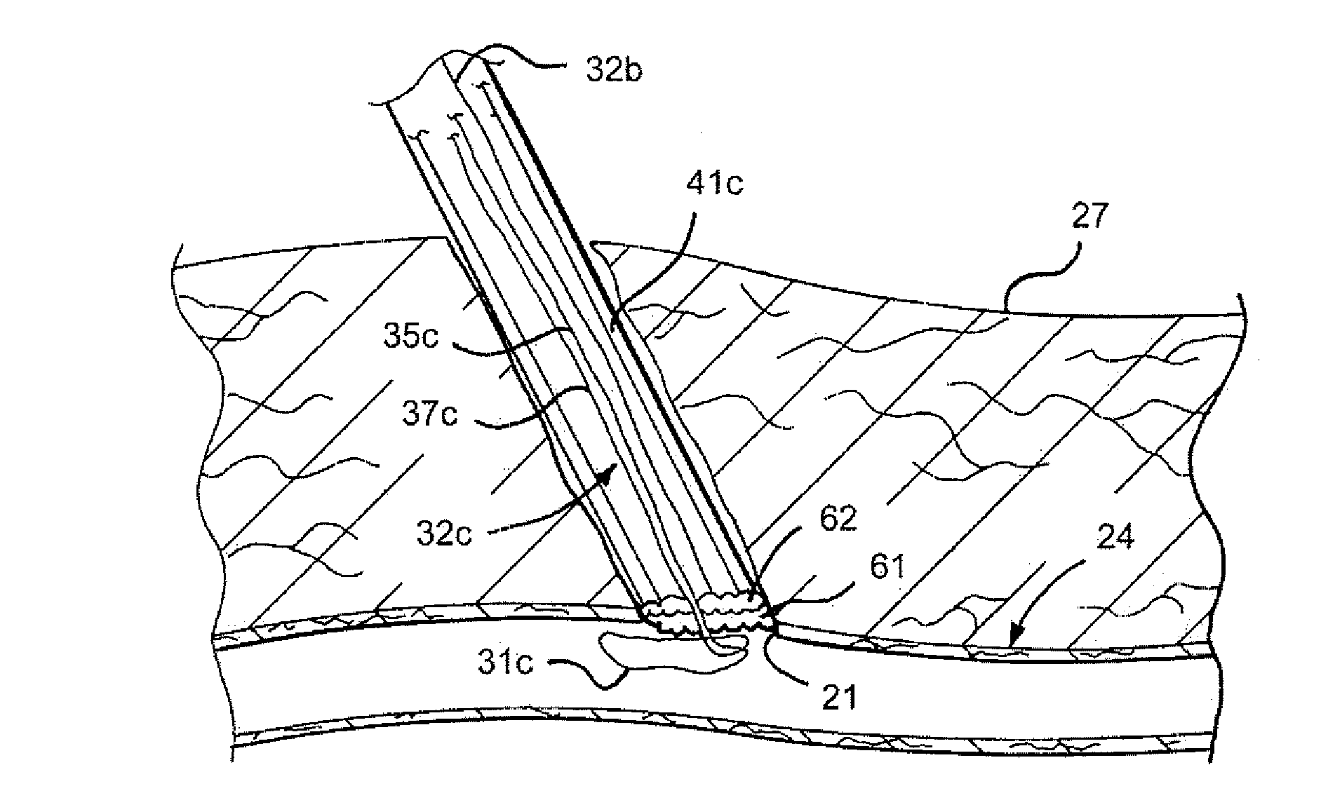
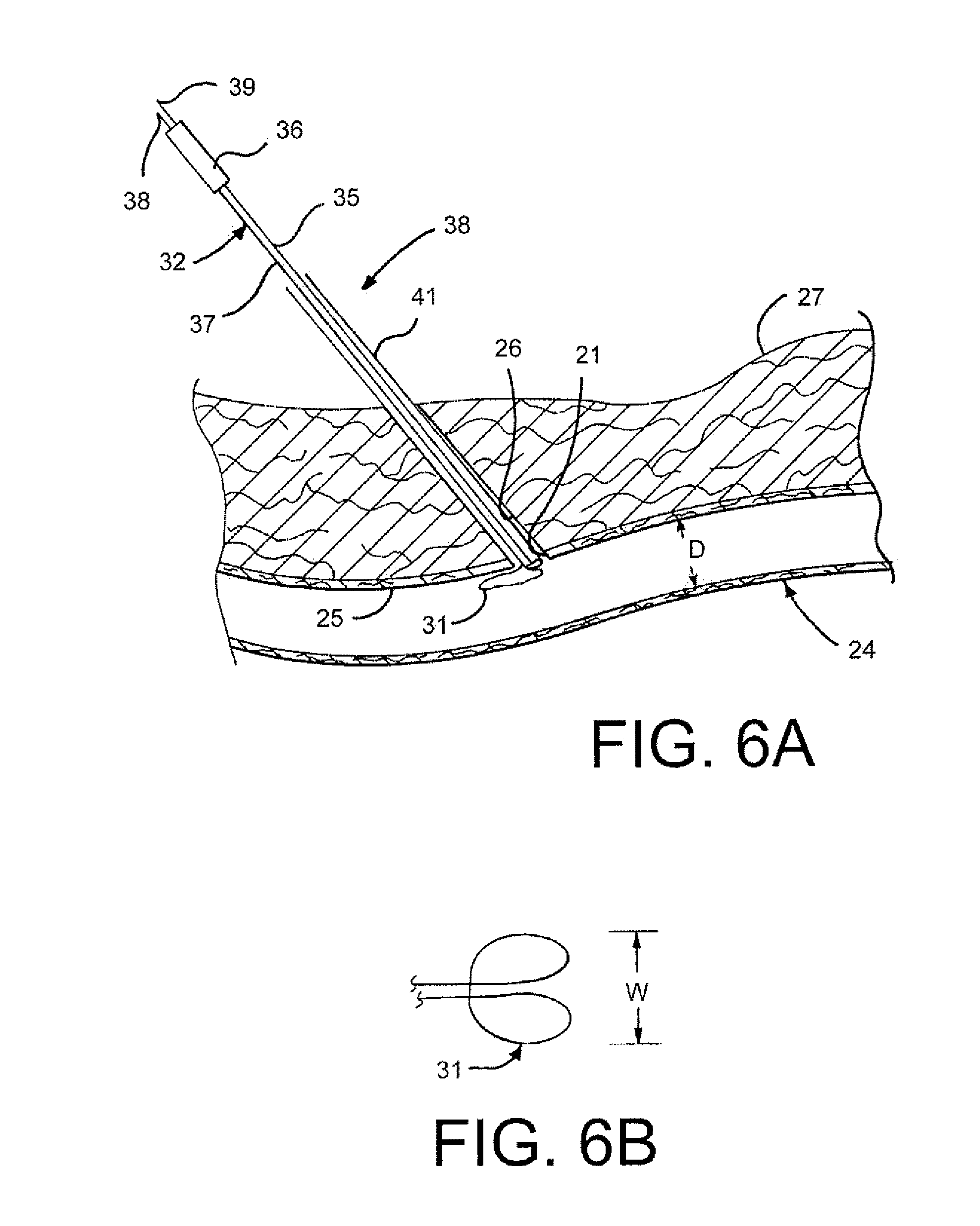
[0055]FIG. 6A illustrates one use for the devices and methods disclosed herein. A patient's skin is shown at 27 with a channel 26 extending therethrough to the vessel 24 In opening 21 has been made in the vessel 24 through which an intravascular procedure has been carried out. As shown in greater detail below in connection with FIGS. 7-10, the device 30 has been inserted through the channel 26 and a collapsible wile foot 31 has been pushed out of a tube 41 into the vessel 24, allowed to expand, and subsequently pulled proximally against the vessel wall 25 The position that the foot 31 assumes against the vessel wall 25 indicates to the physician the general orientation of the opening 21. In the case as shown in FIG. 6A, the opening 21 is along the top side of the vessel 24 or is classified as a “top stick.” When the foot 31 is pulled up against the interior vessel wall 25 in general alignment with the vessel 24, the foot 31 will have twisted or rotated to achieve the position shown ...


PUM


Abstract

A device is disclosed for providing an indication as to the relative position of a vessel or artery opening thereby facilitating the choice of which suturing or plugging technique to thereafter use. A disclosed device includes an outer tube and a collapsible foot slidably disposed within a distal end of the outer tube. The foot is connected to a shaft that passes through the tube and exits a proximal end thereof. The device may further include one or more threaded suture needles, a biodegradable plug or other wound closing device that is connected to another shaft. The collapsed or folded foot is pushed distally out of the tube and through the opening in the vessel whereupon the foot expands. Pulling the expanded foot in the proximal direction provides an indication as to the orientation of the opening in the vessel, which assists in determining the type of closing procedure to be carried out. The shaft connected to the foot is preferably connected to an indicator that indicates to the operator or physician that the vessel opening is in one of three positions on the vessel—left, top or right. As an alternative, the indicator bar may indicate a relative position in degrees, mm or μm in deviation from a top stick (or top position).

Description

CROSS-REFERENCE TO RELATED APPLICATION[0001]This application is a non-provisional patent application claiming priority under 35USC§119(e) to U.S. provisional patent application Ser. No. 60 / 888,208 filed on Feb. 5, 2007FIELD OF THE DISCLOSURE[0002]Methods and apparatuses are disclosed for determining the orientation of a vascular opening on the vessel and thereafter closing said vascular opening. More specifically, systems and methods are disclosed for accurately determining the location of a vascular opening on the vessel so that the appropriate closure technique is employed such as the appropriate suturing technique or plug or pledget technique.BACKGROUND OF THE DISCLOSURE[0003]Various surgical procedures are performed by medical specialists such as cardiologists and radiologists, utilizing percutaneous entry into a blood vessel. To facilitate cardiovascular procedures, a needle is introduced through the skin and into a target blood vessel, often the femoral artery. The needle form...

Claims


Application Information

Patent Timeline
IPC IPC(8): A61B17/04
CPCA61B17/0057A61B17/0469A61B2017/00641A61B2017/00663A61B2017/00867A61B2017/047A61B2017/0472A61B2017/3484A61B2019/467A61B2019/4857A61B2090/067A61B2090/0811
Inventor DRASLER, WILLIAM J.EIDENSCHINK, TRACEETHIELEN, JOSEPH M.JENSON, MARK L.SADASIVA, ANU
Owner BOSTON SCI SCIMED INC
Why Eureka
Try Eureka