Fitting apparatus

a technology of fitting apparatus and fitting rod, which is applied in the direction of electrical programme control, program control, instruments, etc., can solve the problems of easy oscillation of the operation of the robot arm, adversely affecting the assembly, and affecting the fitting of the two workpieces by the robot, so as to achieve quick and stable fitting operation

Active Publication Date: 2008-12-18
FANUC LTD
View PDF7 Cites 44 Cited by
  • Summary
  • Abstract
  • Description
  • Claims
  • Application Information

AI Technical Summary

Benefits of technology

[0015]According to the present invention, even if the force detection means is accompanied by noises due to the vibration of the robot arm or workpiece, the correcting operation is not affected, and a force control gain can be set to a larger value than that in the prior art, thereby making it possible to correct an initial error, if any in the workpieces or the robot arm, quicker than in the prior art. As a result, quick, stable fitting operation can be carried out.

Problems solved by technology

However, between the workpiece held by the robot and the workpiece fixed to the table, there exists a position error and an orientation error, which sometimes adversely affects assembly, or especially, the fitting of the two workpieces by the robot.
However, as the force control gain is increased, the vibration of the robot arm and the vibration due to the contact between the workpieces are liable to be amplified and the operation of the robot arm is easily oscillated.
Therefore, in the conventional compliance control or force control, the force control gain can be increased only to a value determined by the oscillation limit, and in the system having an initial error in the position and orientation of the workpieces and the robot arm, the error correction requires a vast amount of time.

Method used


Image

  • Fitting apparatus
  • Fitting apparatus
  • Fitting apparatus

Examples


Embodiment Construction

[0024]The preferred embodiments of the present invention will be described below with reference to the accompanying drawings.

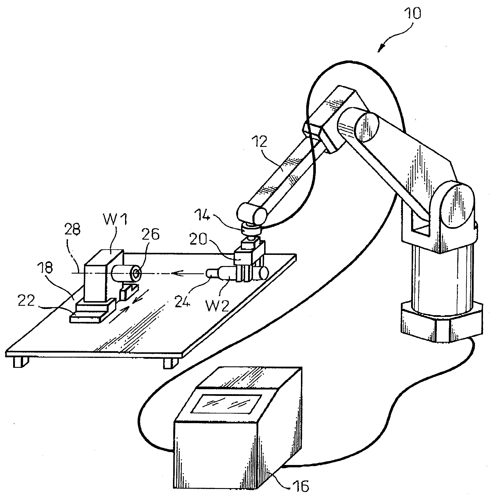
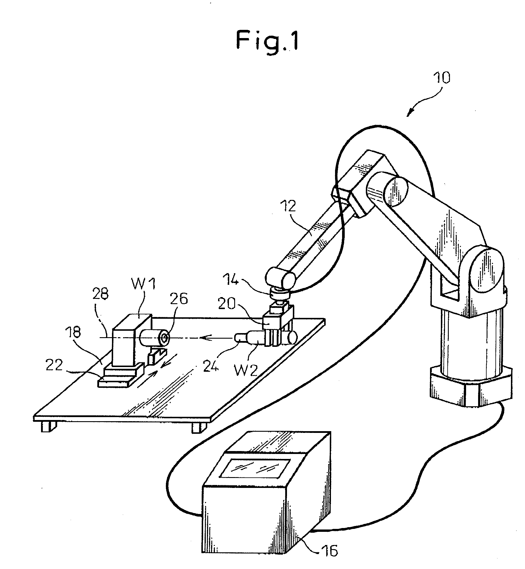
[0025]First, a general configuration of a fitting apparatus 10 according to the present invention will be explained with reference to FIG. 1.

[0026]The fitting apparatus 10 includes a robot arm 12 adapted to be able to move around a plurality of axes, a force detector 14 for detecting a force and a moment, a controller 16 for controlling an operation of robot arm 12, and a table 18 for mounting a workpiece W1 thereon. A gripper 20 adapted to be able to hold and release a workpiece W2 is provided at the forward end of robot arm 12. A clamp unit 22 for fixing workpiece W1 is provided on table 18, so that workpiece W1 to be fitted to workpiece W2 held by gripper 20 can be fixed removably to table 18.

[0027]Force detector 14 is mounted on the wrist of robot arm 12 so that force F and moment M received by workpiece W2 held by gripper 20 can be detected. For example, ...


PUM


Abstract

A fitting apparatus includes a robot arm having, at the forward end thereof, a gripper for holding a workpiece, a force detector for detecting a force and moment received by the workpiece held by the gripper, and a controller for controlling an operation of the robot arm. The controller includes a motion command generating unit for generating an operation command to fit two workpieces to each other, and an operation command correcting unit for correcting the operation command so as to correct the position of the gripper in a direction perpendicular to the fitting direction and the orientation of the gripper around an axis perpendicular to the fitting direction until the detected force and moment become less than or equal to a threshold value, based on either maximum values of the force and moment detected by the force detector while the two workpieces are in contact with each other or the force and moment detected by the force detector when the two workpieces first come into contact with each other.

Description

BACKGROUND OF THE INVENTION[0001]1. Field of the Invention[0002]The present invention relates to a fitting apparatus for fitting two workpieces to each other using a robot while performing compliance control or force control.[0003]2. Description of the Related Art[0004]In carrying out assembly using a robot, it is required to position a workpiece in place on a table while at the same time moving another workpiece accurately to the place with the robot. However, between the workpiece held by the robot and the workpiece fixed to the table, there exists a position error and an orientation error, which sometimes adversely affects assembly, or especially, the fitting of the two workpieces by the robot. In order to solve this problem, a fitting apparatus for fitting two workpieces to each other generally uses a RCC (remote center compliance) mechanism in which a spring or a damper is interposed between the robot arm and the robot gripper to thereby provide a mechanically elastic motion of...

Claims


Application Information

Patent Timeline
Patent Type & Authority Applications(United States)
IPC IPC(8): B25J9/10
CPCB25J9/1633B25J9/1687G05B2219/39529G05B2219/40032
Inventor SATO, TAKASHIYAMAOKA, NOBUAKI
Owner FANUC LTD
Why Eureka
Try Eureka