

Sleep system
- Summary
- Abstract
- Description
- Claims
- Application Information
AI Technical Summary
Benefits of technology
Problems solved by technology
Method used
Image

Examples
Embodiment Construction
[0028]Reference will now be made in detail to the presently preferred embodiments of the invention, examples of which are illustrated in the accompanying drawings.
[0029]Referring generally now to FIGS. 1 through 12, exemplary embodiments of the present invention are shown.
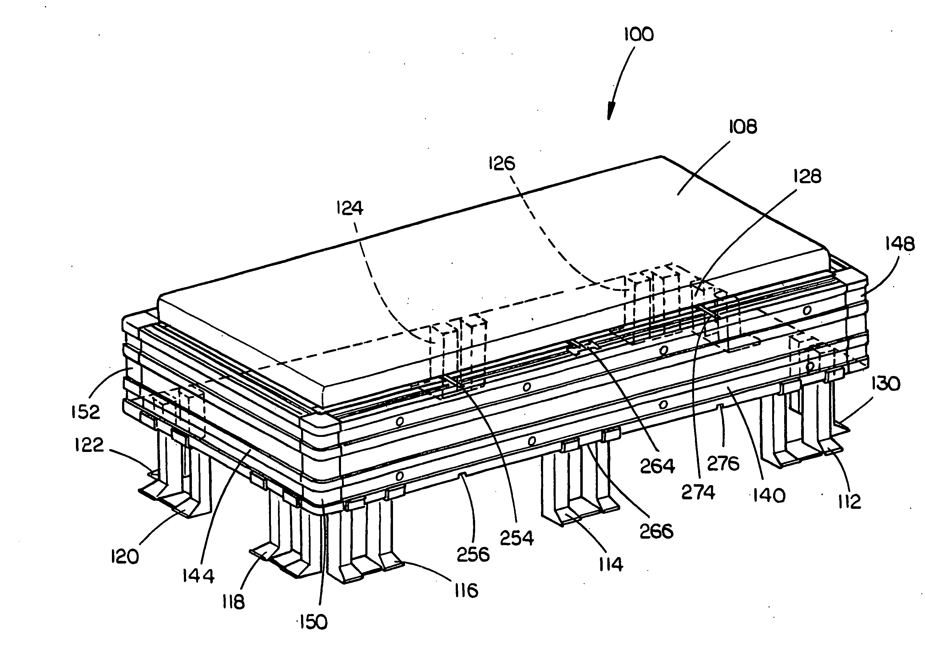
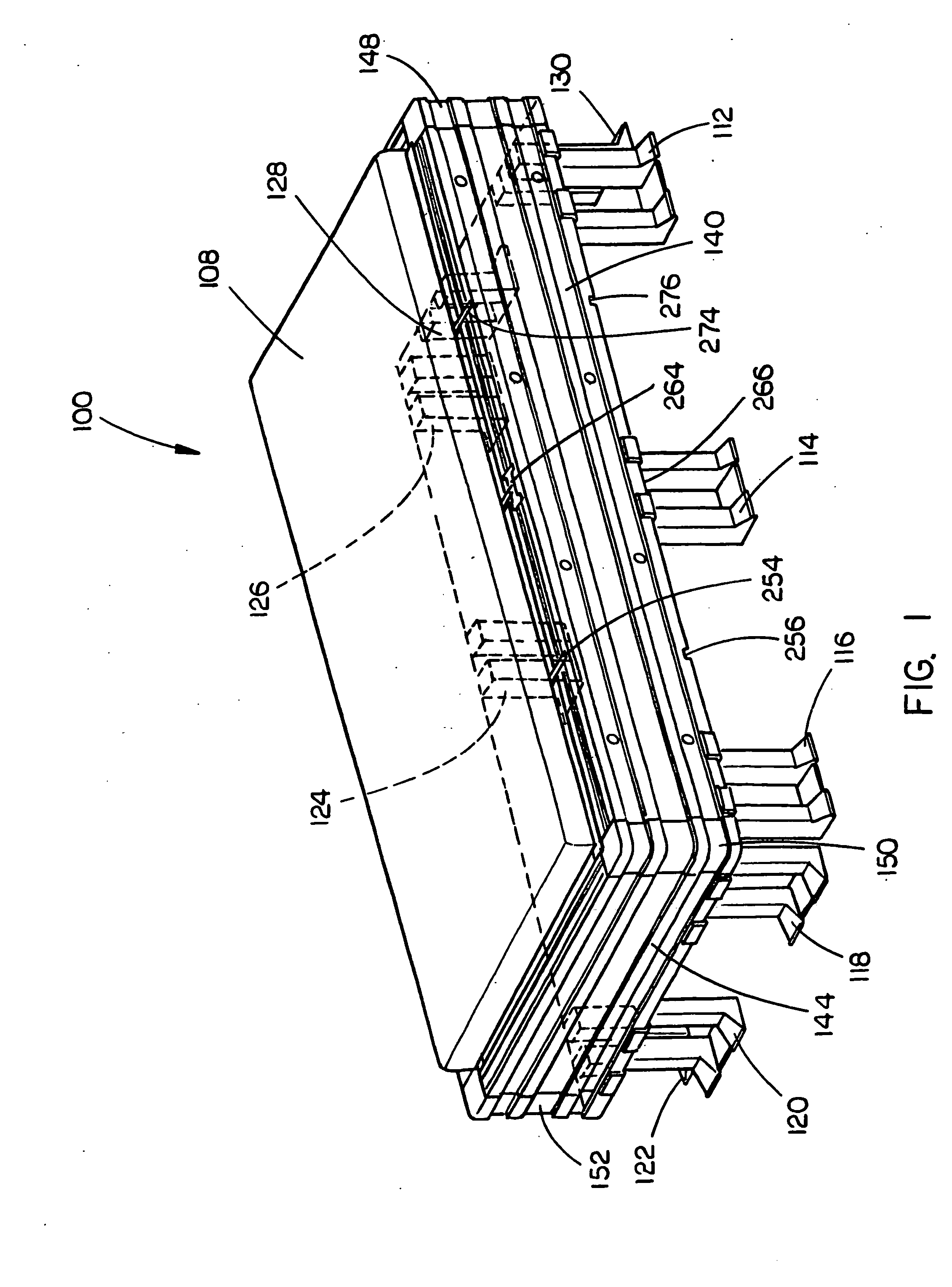
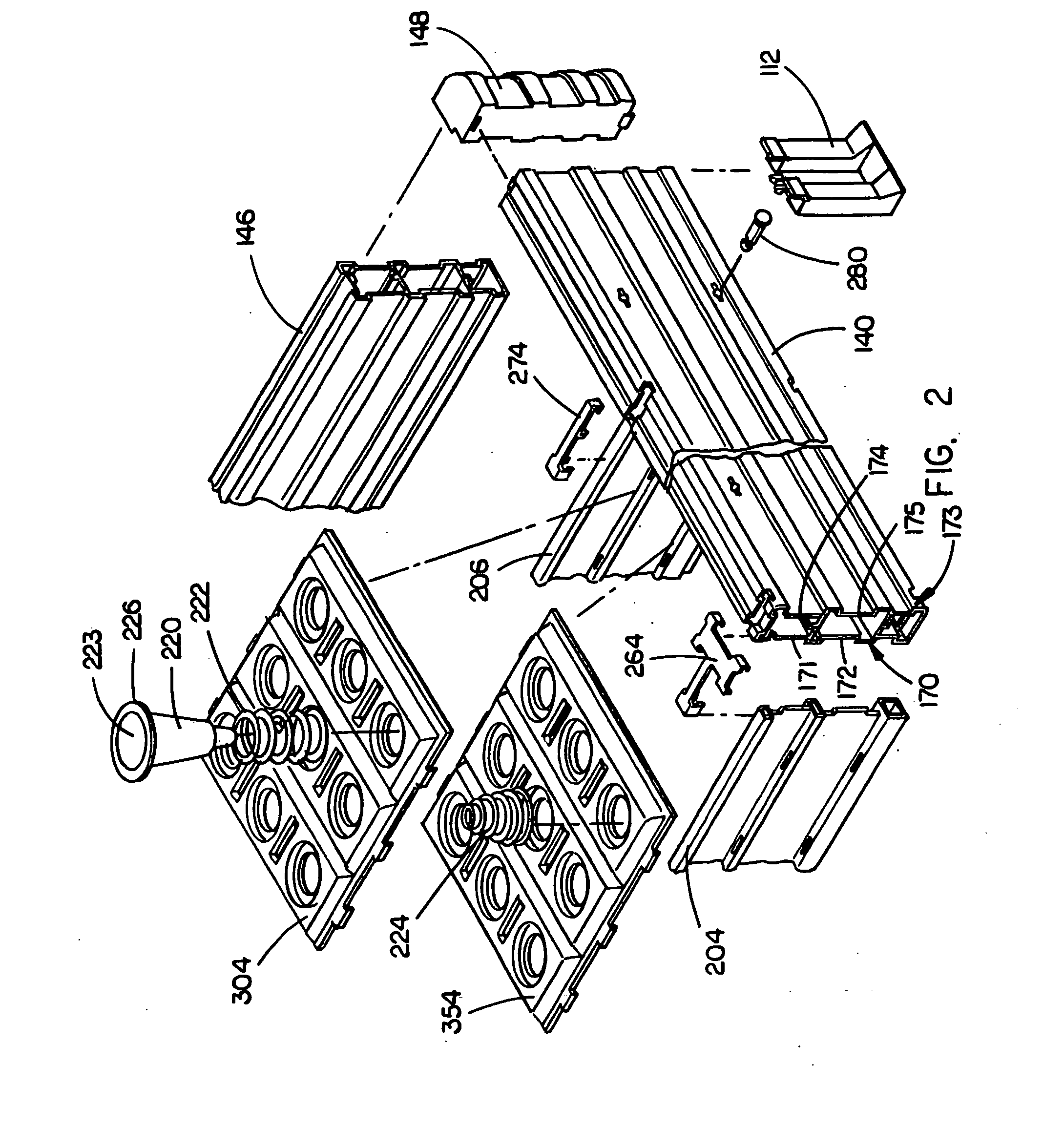
[0030]A sleep system 100 including a frame 102 coupled with a first panel assembly 104 and a second panel assembly 106, the first and second panel assemblies further couple with one another via a sleep support mechanism 110, is shown in FIG. 1. A pad 108 is coupled with the sleep support mechanism 110, the sleep support mechanism 110 providing adjustable support to the pad 108, and the pad 108 further providing a surface for a user to sit upon or lie down on. The frame may be further coupled with a frame support mechanism. In the current embodiment, shown in FIGS. 2, 3, and 4, the sleep system 100 employs a single sleep support mechanism 110. It is understood that any number of sleep support mechanisms may be emplo...
PUM
 Abstract
Description
Claims
Application Information