Refrigerant System With Variable Speed Scroll Compressor and Economizer Circuit

a technology of variable speed scroll compressor and economizer, which is applied in the direction of liquid fuel engine, domestic cooling apparatus, lighting and heating apparatus, etc., can solve the problems of inability to use scroll compressor type in combination with variable speed drive for its motor, increase or decrease etc., to achieve the effect of increasing or decreasing the capacity of the refrigerant system

Inactive Publication Date: 2008-12-25
CARRIER CORP
View PDF34 Cites 16 Cited by
  • Summary
  • Abstract
  • Description
  • Claims
  • Application Information

AI Technical Summary

Benefits of technology

[0008]In a disclosed embodiment of this invention, a scroll compressor is provided in a refrigerant system with an economizer circuit. The scroll compressor has a motor that is driven by a variable speed drive. By selectively utilizing the economizer circuit, and / or the optional unloader function the controller can increase or decrease the capacity of the refrigerant system. Further, by varying the speed of the motor, capacities in each mode of operation can be additionally adjusted to provide essentially continuous stepless control.
[0010]By providing the variable speed drive in combination with the capacity adjustment options mentioned above, the present invention allows an end user to exactly tailor the system capacity and / or efficiency or combination of these two parameters to a desired level. The method of operation described above would be especially suitable for a transportation refrigeration applications, such as for example container refrigeration units, tractor-trailer units or buses, where a wide operating range of capacity is desired, while at the same time a precise capacity level control is also needed to maintain the cargo or the cooled environment within a narrow temperature range. As also common in these refrigeration applications, an additional throttling device, often called suction modulation valve (SMV) is provided to further reduce the capacity to the level below the level that would be normally achievable through unloading mechanisms and reduction in motor speed. The application of the variable speed drive can diminish or even in certain instances eliminate the need for an additional SMV.

Problems solved by technology

However, the capacity provided by these functions is increased or decreased in steps.
However, this type of scroll compressor has not been utilized in combination with a variable speed drive for its motor.

Method used


Image

  • Refrigerant System With Variable Speed Scroll Compressor and Economizer Circuit
  • Refrigerant System With Variable Speed Scroll Compressor and Economizer Circuit
  • Refrigerant System With Variable Speed Scroll Compressor and Economizer Circuit

Examples


Embodiment Construction

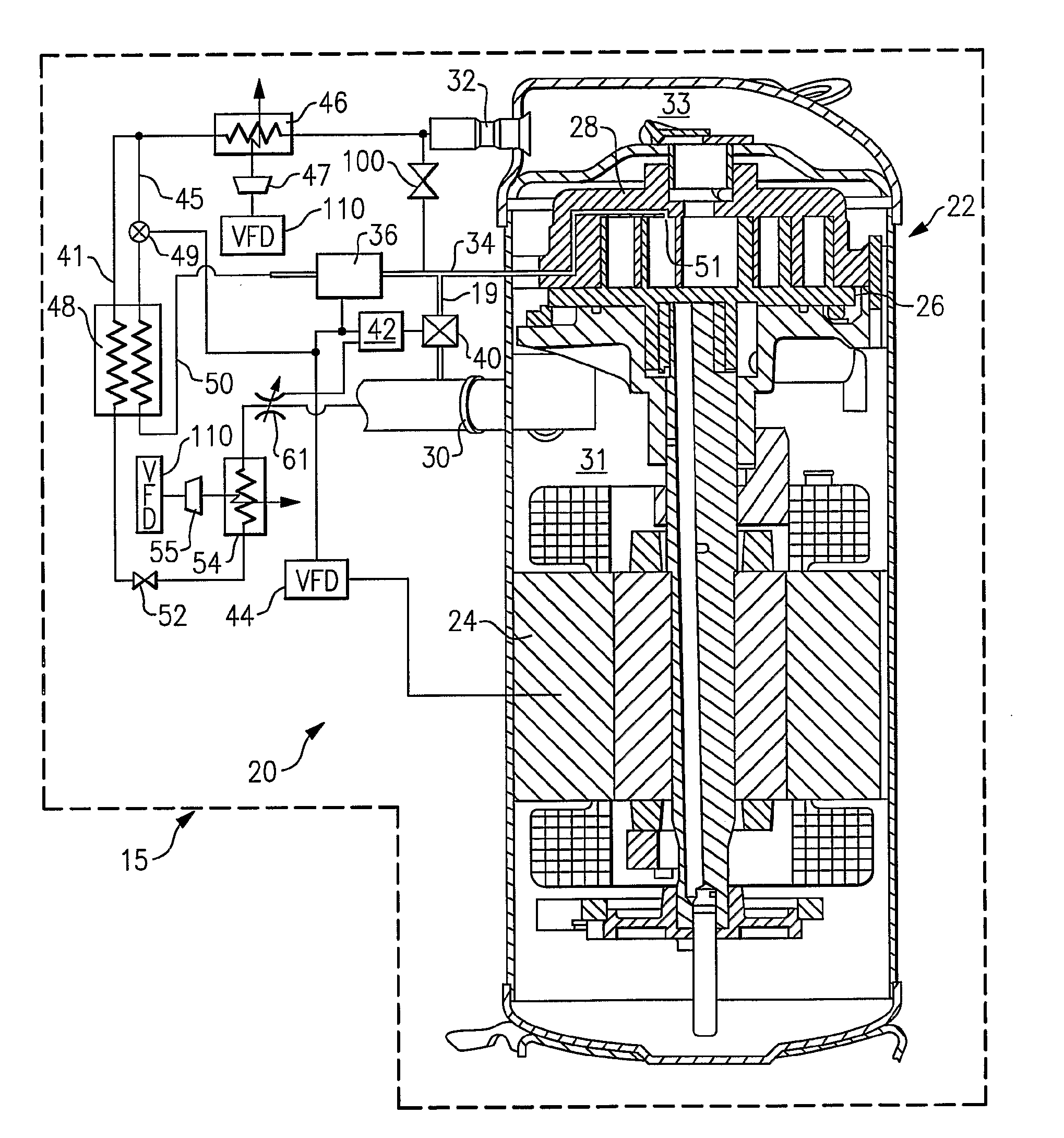
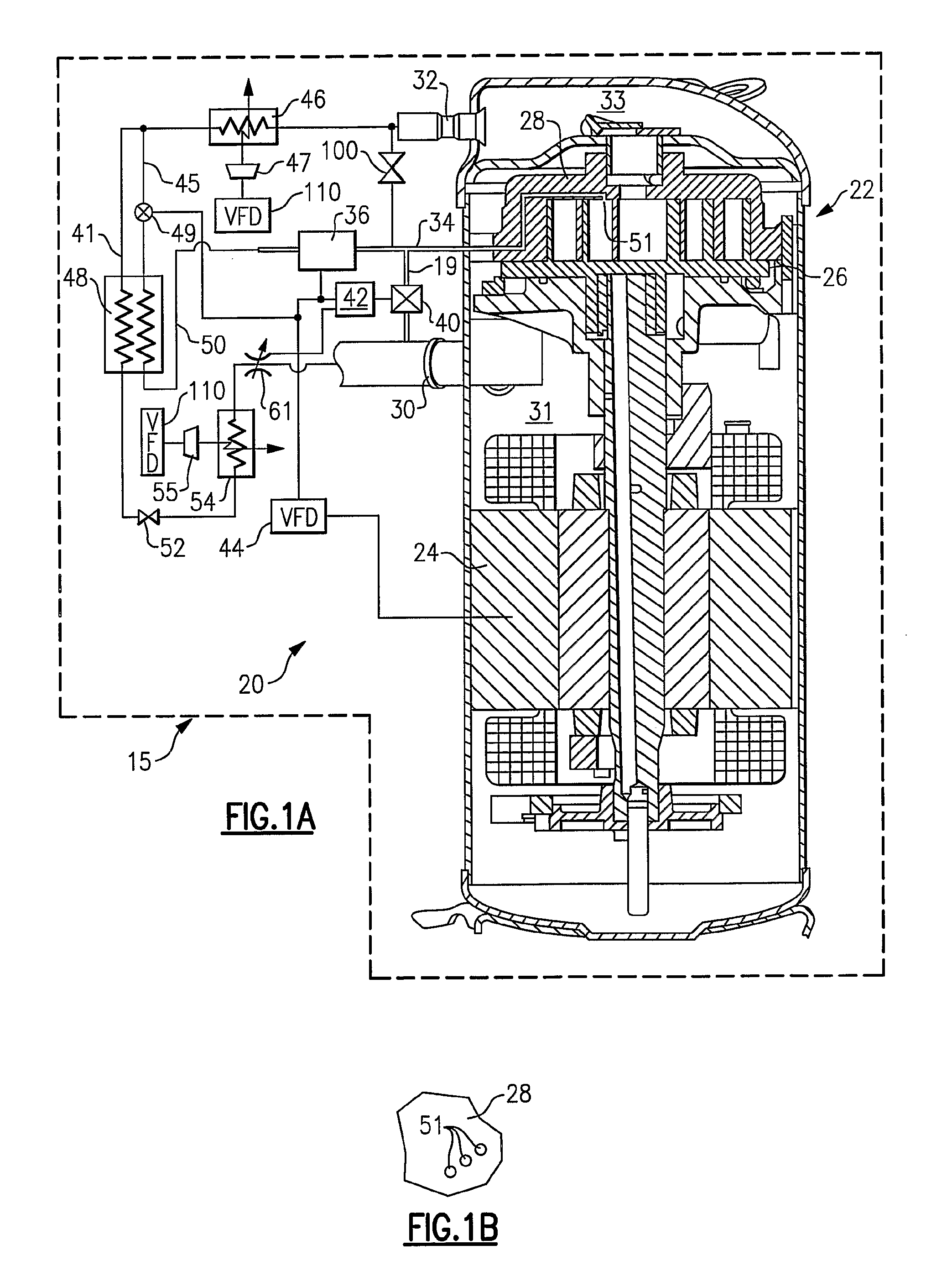
[0022]A refrigerant system 20 is illustrated in FIG. 1A having a single stage compressor 22, a controller 42, a variable speed drive 44 and other components as illustrated in this Figure. As is known, a motor 24 for the compressor 22 can be driven at a variety of speeds such that the amount of refrigerant compressed by the compressor 22 can be varied. The compressor 22 is a scroll compressor having an orbiting scroll member 26 and a non-orbiting scroll member 28. As is known, a number of compression chambers are defined between the two scroll members to compress an entrapped refrigerant when the orbiting scroll member 26 is driven to orbit by the electric motor 24. As can be seen, a suction tube 30 leads refrigerant into a suction chamber 31 surrounding the motor and leading into the compression chambers. Once the refrigerant is compressed, it is driven into a discharge chamber 33 communicating with a discharge port 32. The structure of a scroll compressor is known. As also shown, a...


PUM


Abstract

A scroll compressor system having a variable speed drive is utilized. By providing the economizer and / or bypass functions along with the variable speed drive, precise capacity adjustment between the discrete steps is achieved to exactly match load demands at a wide spectrum of operating conditions.

Description

BACKGROUND OF THE INVENTION[0001]This invention relates to a variable speed scroll compressor that is operable in a refrigerant system with an economizer function and other means of capacity modulation.[0002]Refrigerant systems are utilized in many applications to condition an environment. In particular, air conditioners and heat pumps are employed to cool and / or heat a secondary fluid such as air entering an environment. The cooling or heating load of the environment may vary with ambient conditions, occupancy level, other changes in sensible and latent load demands, and as the temperature and / or humidity set points are adjusted by an occupant of the building.[0003]Thus, refrigerant systems can be provided with sophisticated controls, and a number of optional components and features to adjust cooling and / or heating capacity. Known options include the ability to bypass refrigerant which has been at least partially compressed by a compressor back to a suction line. This function is a...

Claims


Application Information

Patent Timeline
Patent Type & Authority Applications(United States)
IPC IPC(8): F25B1/00F01C1/02F25D17/06F25D3/00
CPCB60H1/3216B60H2001/3272F25B1/04F25B1/10F25B49/02F25B49/025F25B2400/13F25B2600/0253F25B2600/0261F25B2600/11F25B2600/2501
Inventor LIFSON, ALEXANDERTARAS, MICHAEL F.
Owner CARRIER CORP
Why Eureka
Try Eureka