Solvent delivery pump

Inactive Publication Date: 2011-12-29
SHIMADZU CORP
View PDF4 Cites 5 Cited by
  • Summary
  • Abstract
  • Description
  • Claims
  • Application Information

AI Technical Summary

Benefits of technology

[0015]As described above, because the solvent delivery pump in the invention is provided with the resin capacity decreasing member covering at least the portion of the inner wall of the pump chamber to fill the clearance from the plunger,

Problems solved by technology

If there is a large space between the inner wall of the pump chamber and the outside shape of the plunger, an amount of solution receiving compression (compression capacity) when the plunger is at the top dead center is large, which causes pulsation of solution sending.
If the compression capacity in the pump chamber is large, time taken for an interior of the pump chamber to return to atmospheric pressure at the time of sucking of the solution becomes long and high pressure is applied on a seal member for a long time to reduce durability of the seal member.
If the high pressure is applied on such a seal member for an extended amount of time, it significantly shortens life of the seal member.
However, if a clearan

Method used


Image

  • Solvent delivery pump
  • Solvent delivery pump
  • Solvent delivery pump

Examples


Example

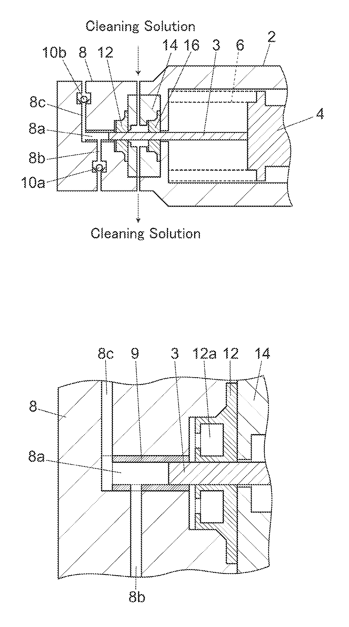
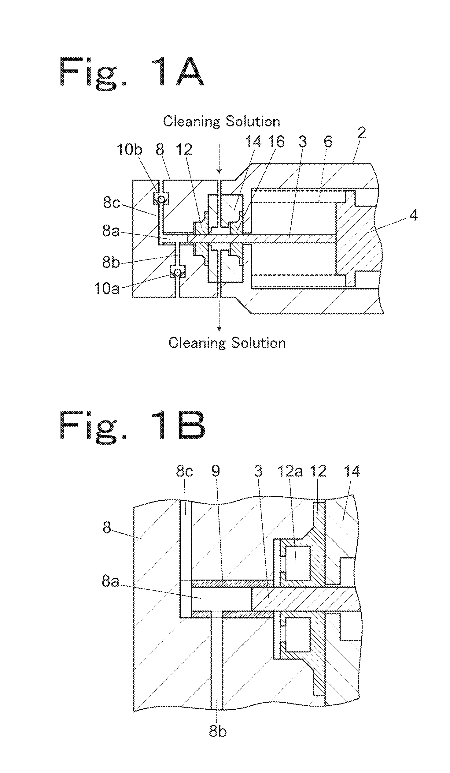
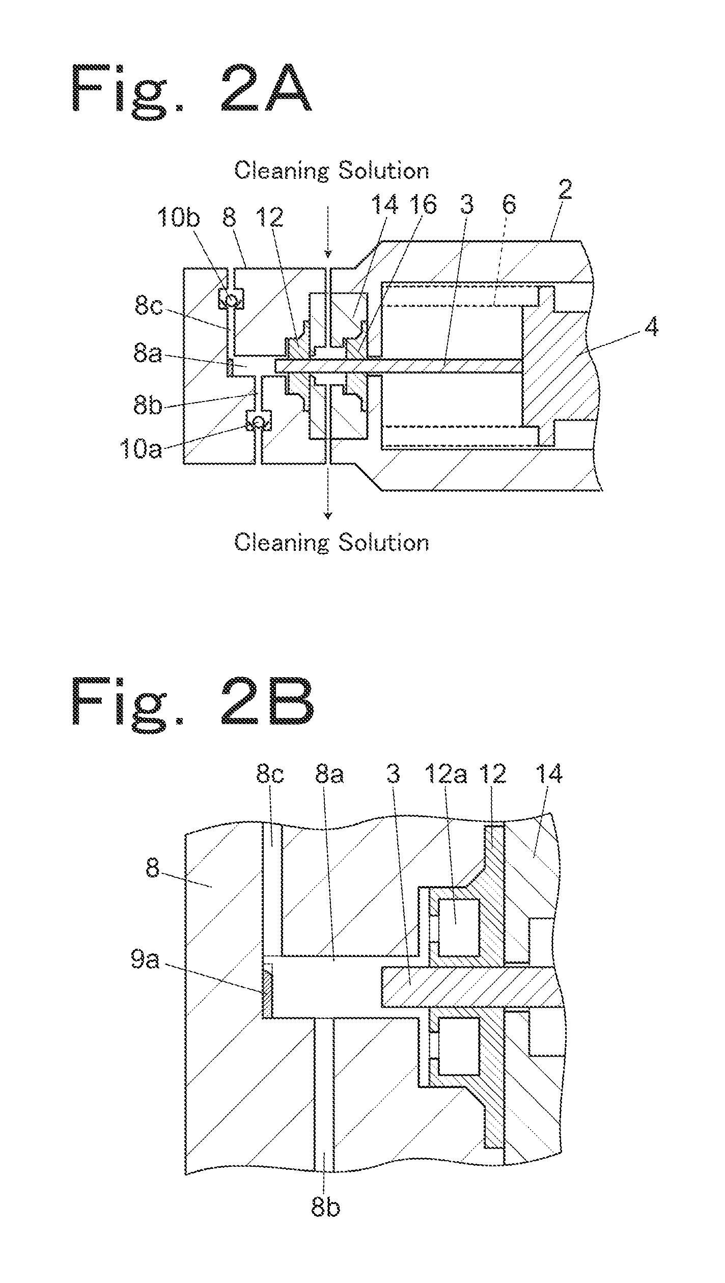
[0020]A first example of a solvent delivery pump will be described by using FIGS. 1A and 1B. The solvent delivery pump in the example includes a syringe 2 and a pump head 8. The syringe 2 houses in itself a cross head 4. The cross head 4 retains an end face on a base end side of the plunger 3 and is pushed against a peripheral face of a cam (not shown) by an elastic force of a spring 6. When the cam is rotated by a driving motor (not shown), the cross head 4 and the plunger 3 reciprocate following the peripheral face of the cam.

[0021]The pump head 8 is mounted to the syringe 2. The pump head 8 includes a pump chamber 8a, a solution sucking flow path 8b, and a solution discharge flow path 8c so as to suck and discharge a solution by reciprocation of a tip end portion of the plunger 3 retained on the cross head 4. The solution sucking flow path 8b and the solution discharge flow path 8c are respectively provided with check valves 10a and 10b for utilizing changes in pressure in the pu...


PUM


Abstract

A solvent delivery pump is provided, which includes: a cylindrical pump chamber, an inside of which is made of metal; a plunger inserted from a tip end into the pump chamber to reciprocate in a certain direction to increase and decrease a capacity in the pump chamber; a capacity decreasing member made of resin and covering at least a portion of an inner wall of the pump chamber to reduce a clearance from the plunger; and a seal member provided to a plunger insertion portion of the pump chamber to come in sliding contact with an outer peripheral face of the plunger to seal the pump chamber. Preferable examples of the capacity decreasing member are a cylindrical sleeve covering at least a portion of an inner peripheral face of the pump chamber, a spacer disposed on an innermost face of the pump chamber to reduce a clearance from a tip end face of the plunger which has reached a top dead center, or both of the sleeve and the spacer.

Description

BACKGROUND OF THE INVENTION[0001]1. Field of the Invention[0002]The present invention relates to a solvent delivery pump for sucking and discharging a solution by reciprocating a plunger in a pump chamber.[0003]2. Description of the Related Art[0004]A common plunger-type solvent delivery pump sucks a solution into a pump chamber and discharges the sucked solution with a plunger reciprocating in the cylindrical pump chamber to vary a capacity in a space in the pump chamber. In general, sapphire is used as material of the plunger, and stainless steel is used as material of the pump chamber.[0005]In such a solvent delivery pump, a space between an inner wall of the pump chamber and an outside shape of the plunger is designed to be as small as possible when the plunger has reached a top dead center (when discharge of the solution has been finished and sucking of the solution is to be started). If there is a large space between the inner wall of the pump chamber and the outside shape of ...

Claims


Application Information

Patent Timeline
IPC IPC(8): A61M1/00
CPCF04B13/00F05C2225/00F04B53/16
Inventor ASO, YOSHIAKI
Owner SHIMADZU CORP
Why Eureka
Try Eureka