Refrigerant system with multi-speed scroll compressor and economizer circuit

a scroll compressor and economizer technology, which is applied in refrigeration components, transportation and packaging, light and heating equipment, etc., can solve the problems of unusable scroll compressors and relatively large discrete steps of the capacity provided by these functions, and achieve the effect of increasing or decreasing the capacity of the refrigerant system and additional control flexibility

Inactive Publication Date: 2007-06-14
SCROLL TECH
View PDF3 Cites 52 Cited by
  • Summary
  • Abstract
  • Description
  • Claims
  • Application Information

AI Technical Summary

Benefits of technology

[0009] In a disclosed embodiment of this invention, a scroll compressor is provided in a refrigerant system with an economizer circuit. The scroll compressor has a motor that can be driven at multiple discreet speeds. For illustration purposes, the discussion below deals with a two-speed motor. However, the scroll compressor can be run at more than two distinct speeds. By selectively utilizing the economizer circuit, and / or an optional unloader function, the controller can increase or decrease the capacity of the refrigerant system. Further, by varying the speed of the motor, system capacity within each mode of operation can be adjusted to provide additional control flexibility.
[0011] By providing the two-speed drive in combination with the capacity adjustment options mentioned above, the present invention allows an end user to closely tailor the system capacity and / or efficiency, or a combination of these two parameters, to a desired level. As also known, an additional throttling device, often called a suction modulation valve (SMV) may be provided to further reduce the capacity to the level below the level that would be normally achievable through the unloading mechanisms and reduction in motor speed.

Problems solved by technology

However, the capacity provided by these functions is increased or decreased in relatively large discrete steps.
However, scroll compressors have not been utilized in combination with a two-speed drive for its motor and an economizer cycle to obtain additional flexibility in system operation and control.

Method used


Image

  • Refrigerant system with multi-speed scroll compressor and economizer circuit
  • Refrigerant system with multi-speed scroll compressor and economizer circuit
  • Refrigerant system with multi-speed scroll compressor and economizer circuit

Examples


Embodiment Construction

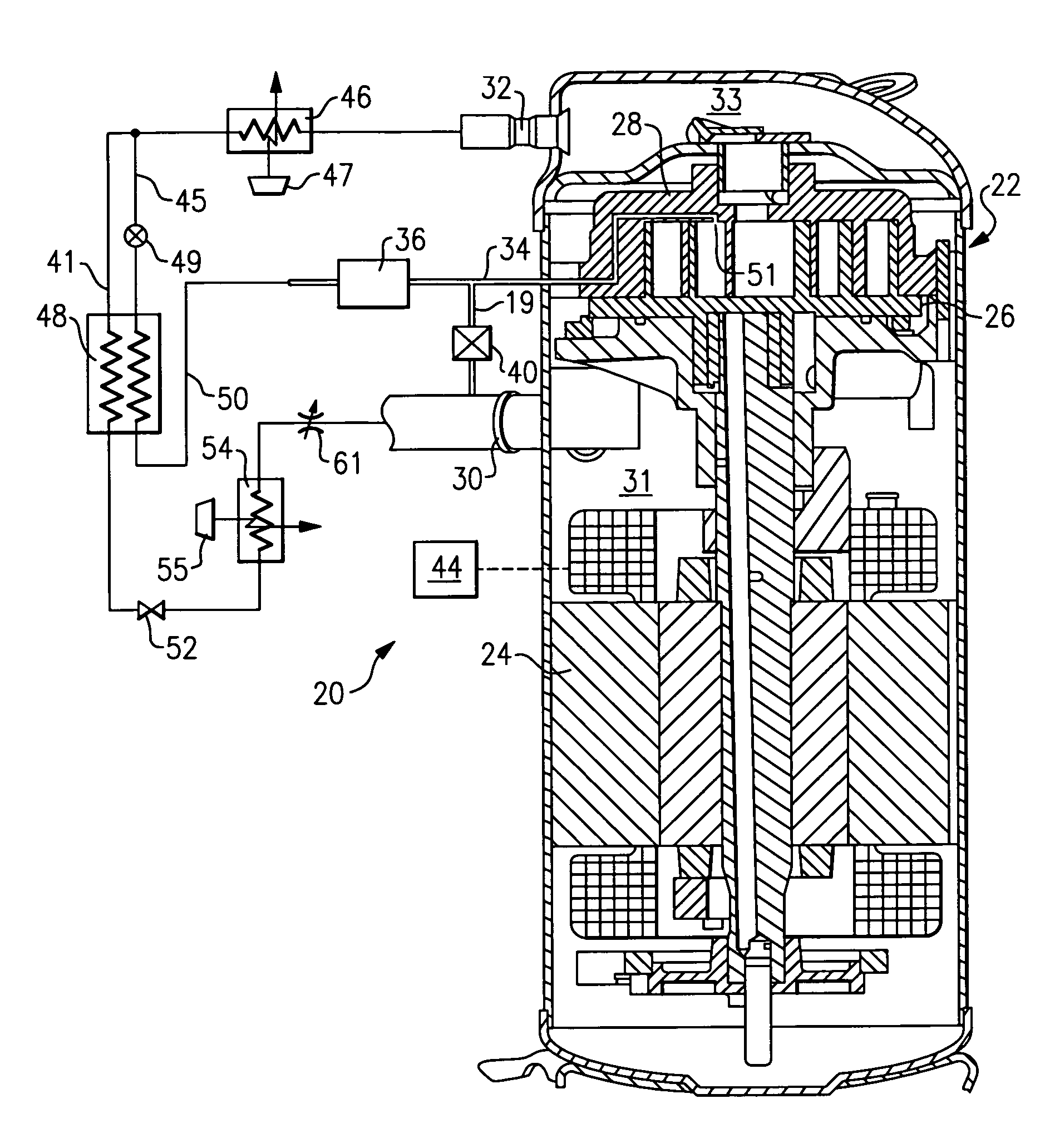
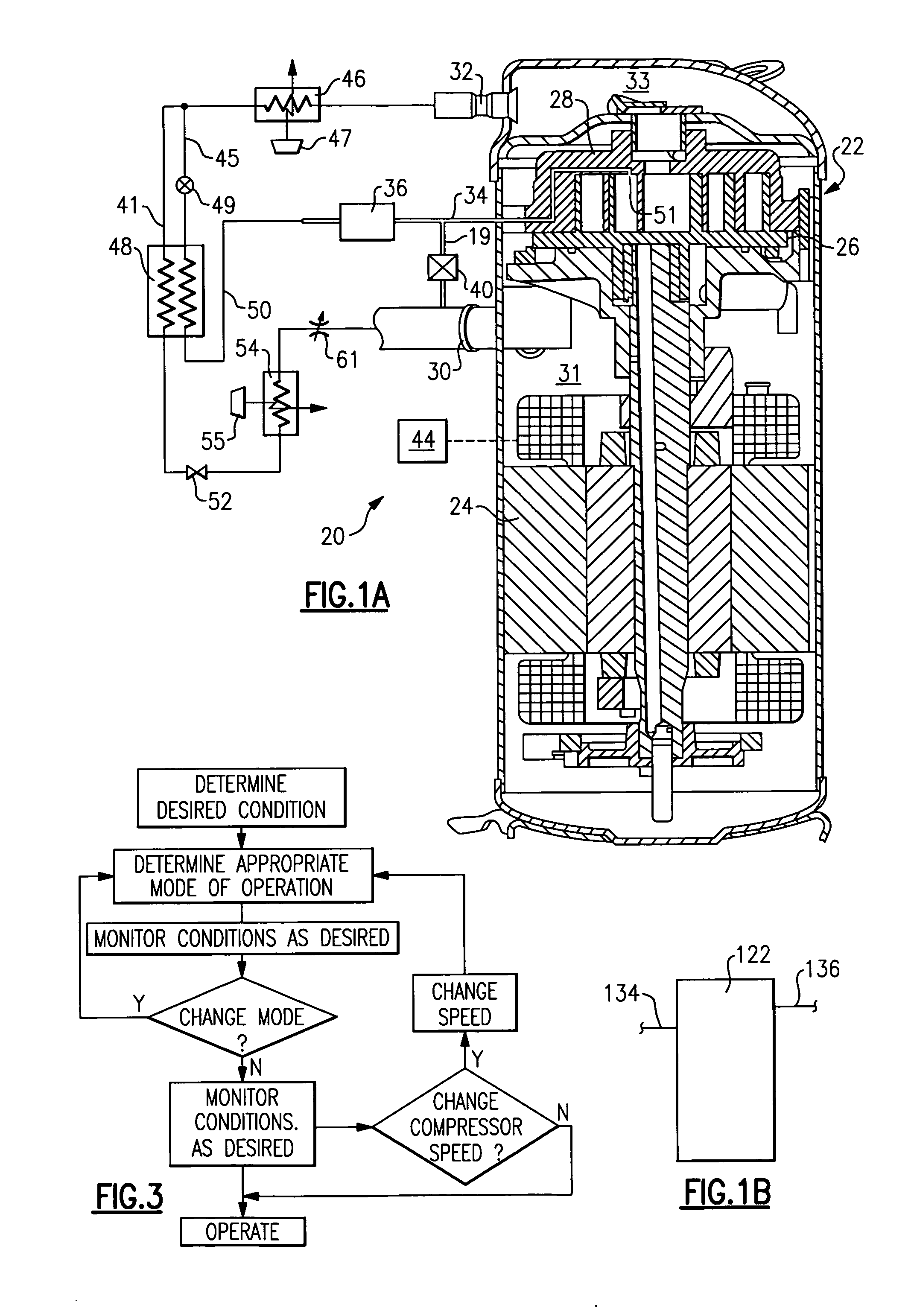
[0018] A refrigerant system 20 is illustrated in FIG. 1A having a compressor 22 and a controller 44. As is known, a motor 24 for the compressor 22 can be driven at two speeds such that the amount of refrigerant compressed and circulated throughout the system by the compressor 22 can be varied. That is, the compressor can be driven at one of two non-zero speeds at steady state operation. The compressor 22 is a scroll compressor having an orbiting scroll member 26 and a non-orbiting scroll member 28. As is known, a number of compression chambers are defined between the two scroll members to compress an entrapped refrigerant when the orbiting scroll member 26 is driven to orbit by the electric motor 24. As can be seen, a suction tube 30 leads refrigerant into a suction chamber 31 surrounding the motor and leading into the compression chambers. Once the refrigerant is compressed, it is driven into a discharge chamber 33 communicating with a discharge port 32. The general structure of a ...


PUM


Abstract

A scroll compressor is provided with a multiple-speed motor. A control selects a speed for operating the motor, along with selecting between several available options for the system capacity adjustment to meet external load demands in a most efficient and reliable manner. The disclosed embodiment includes an economizer circuit, an unloader function, and an optional suction modulation valve. By utilizing each of these features in combination with the multi-speed motor for the compressor, the present invention is better able to tailor provided capacity to desired capacity.

Description

BACKGROUND OF THE INVENTION [0001] This invention relates to a two-speed scroll compressor that is operable in a refrigerant system with an economizer function and other means of capacity modulation. [0002] Refrigerant systems are utilized in many applications to condition an environment. In particular, air conditioners and heat pumps are employed to cool and / or heat a secondary fluid such as air entering an environment. The cooling or heating load of the environment may vary with ambient conditions, occupancy level, other changes in sensible and latent load demands, and as the temperature and / or humidity set points are adjusted by an occupant of the building. [0003] Thus, refrigerant systems can be provided with sophisticated controls, and a number of optional components and features to adjust cooling and / or heating capacity. Known options include the ability to bypass refrigerant which has been at least partially compressed by a compressor back to a suction line. This function is ...

Claims


Application Information

Patent Timeline
Patent Type & Authority Applications(United States)
IPC IPC(8): F25B41/00F25B49/00
CPCB60H1/3216B60H2001/3272F25B1/04F25B1/10F25B49/02F25B49/025F25B2400/13F25B2600/0253F25B2600/0261F25B2600/11F25B2600/2501
Inventor LIFSON, ALEXANDERTARAS, MICHAEL F.
Owner SCROLL TECH
Why Eureka
Try Eureka