Filter Module

a filter module and filter insert technology, applied in the field of filter modules, can solve the problems of waste of fluid during the use of the filter device, and laborious and tedious maintenance or replacement of the filter rods, and achieve the effect of easy handling of the filter inserts, high workpiece precision level and quality

Inactive Publication Date: 2008-12-25
DEXWET USA
View PDF13 Cites 51 Cited by
  • Summary
  • Abstract
  • Description
  • Claims
  • Application Information

AI Technical Summary

Benefits of technology

[0008]A further advantageous effect is achieved with a configuration involving multiple filter inserts, especially if multiple rows of filter elements, preferably the individual filter groups, each with its own filter bracket, are combined. This allows the individual filter rows or filter groups to be cleaned or replaced independently of one another, based upon the degree of soiling, thereby reducing the cost of exchanging the filter inserts, since filter inserts that are still usable can continue to be used.
[0045]According to a further embodiment, the filter module can be equipped at the outlet opening, in other words at the visible front side, with a covering grid plate. This offers protection against unintended contact with the filter elements, especially if these are wetted with fluid, while also offering visual design possibilities for the front side of the filter module. With a lamellar configuration of the grate rods, the flow of the exiting, filtered air can also be influenced, for example deflecting it in a specific direction. For attaching the covering grid plate, all possible types of attachment, such as screws, clamps, adhesives, etc, are again possible.BRIEF DESCRIPTION OF THE DRAWINGS

Problems solved by technology

The disadvantage of this system is that each of the filter rods is mounted separately in the filter housing, so that maintenance or replacement of the filter rods is correspondingly laborious and tedious.
Also disadvantageous is that the fluid is consumed when the filter device is in use, and the fluid container must be regularly refilled to extend its useful period, to maintain the wetting of the filter rods.
This filling process requires a great deal of caution or additional accessories to prevent contamination.
Independent of the supply with fluid, if the filter rods are badly soiled following an extended period of use or due to severely polluted machine exhaust, a reconditioning cleaning or replacement of the filter rods or of the entire filter device may be necessary, which, because of the individually attached filter rods, entails high costs from increased handling expenses or a complete replacement.
With the mentioned filter media it is somewhat difficult to produce complicated cross-sectional shapes, which is why in these cases a subsequent application on the surface of the filter elements is easier to produce.

Method used


Image

  • Filter Module
  • Filter Module
  • Filter Module

Examples


Embodiment Construction

[0055]By way of introduction, it is noted that in the differently described embodiments, equivalent parts are designated by the same reference symbols or component descriptions, wherein the disclosures contained in the entire description can be logically transferred to equivalent parts having the same reference symbols or the same component descriptions. Also, positional information selected in the description, such as above, below, to the side, etc., refers to the immediately described or illustrated figure, and, in the case of a position change, can be logically transferred to the new position. Furthermore, individual characterizing features or combinations of features from the illustrated and described exemplary embodiments can also represent solutions that are independent, inventive or specified in the invention.

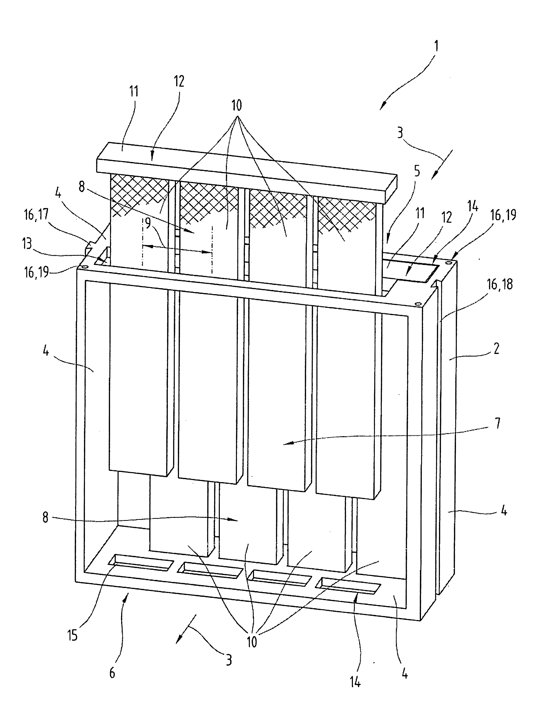
[0056]FIG. 1 shows an embodiment of a filter module 1 according to the invention for removing air-polluting materials from machine exhaust. The exhaust air can come from...


PUM

PropertyMeasurementUnit
center-to-center distanceaaaaaaaaaa
surface areaaaaaaaaaaa
shapeaaaaaaaaaa

Abstract

The invention relates to a filter module for removing air-polluting materials from machine exhaust, comprising a filter housing with an intake opening and an outlet opening for channeling machine exhaust through, at least one mounting element for mounting the filter module on a machine, and a filter assembly, arranged in the filter housing and comprised of at least two filter groups, arranged in tandem in the direction of flow and comprised of rod-shaped filter elements with a filter medium, said elements being arranged parallel to one another at a constant center-to-center distance and with their longitudinal axis largely crosswise to the direction of flow, wherein the filter elements of two adjacent filter groups are parallel to one another, and are arranged offset in relation to one another, crosswise to their longitudinal axes and to the direction of flow. The filter elements are connected with at least one filter bracket to form at least one filter insert, and the filter insert is detachably connected to the filter housing.

Description

CROSS-REFERENCE TO RELATED APPLICATIONS[0001]This application is a national stage of and claims the benefit of priority of International Patent Application No. PCT / AT2005 / 000359, filed on Sep. 9, 2005, which is relied on and incorporated herein by reference.BACKGROUND OF THE INVENTION[0002]The invention relates to a filter module for removing air-polluting materials from machine exhaust, comprising a filter housing with an intake opening and an outlet opening for channeling machine exhaust through, at least one mounting element for mounting the filter module on a machine, and a filter assembly, arranged in the filter housing and comprised of at least two filter groups, arranged in tandem in the direction of flow and comprised of rod-shaped filter elements with a filter medium, said elements being arranged parallel to one another at a constant center-to-center distance and with their longitudinal axis largely crosswise to the direction of flow, wherein the filter elements of two adja...

Claims


Application Information

Patent Timeline
Patent Type & Authority Applications(United States)
IPC IPC(8): B01D47/00B01D46/24B01D50/00
CPCB01D45/12B01D46/0035B01D47/00Y10T29/49826B01D2273/10B01D46/0005B01D53/18B01D45/10
Inventor PETELN, ERICH
Owner DEXWET USA
Why Eureka
Try Eureka