LED lighting lamp

a technology of led lighting lamps and led lamps, which is applied in the direction of discharge tubes/lamp details, gas-filled discharge tubes, coupling device connections, etc., can solve the problems of lowering reliability as a lighting lamp, reducing the degree of freedom of selection of members, and reducing the reliability of led lighting lamps. , to achieve the effect of enhancing reliability and long-term stability, avoiding heat-induced damage of light-emitting diodes, and increasing degree of freedom in selecting members

Inactive Publication Date: 2011-02-01
CITIZEN ELECTRONICS CO LTD
View PDF11 Cites 7 Cited by
  • Summary
  • Abstract
  • Description
  • Claims
  • Application Information

AI Technical Summary

Benefits of technology

[0010]Because the LED lighting lamp according to the present invention includes the lamp body and the socket in which the lamp body is fitted, soldering of the light emitting diodes is not required, and a reflow process is therefore not required. Consequently, heat-induced damage of the light emitting diodes can be avoided, and reliability and long-term stability of the LED lighting lamp are enhanced. In addition, because there is no need to take heat-resistance into account, there arise the advantageous effects that the degree of freedom in selecting members is increased and selection of materials is made easier. Moreover, because there is no need to substitute entire fittings when exchanging a light source of the LED lighting lamp, a low exchange cost can be achieved.

Problems solved by technology

Heat generated by soldering is transmitted to the light emitting diodes through the leads 93a, and therefore, a possibility arises that the light emitting diodes 93 are thermally damaged; thus lowering reliability as a lighting lamp.
Moreover, there is a problem that when the lighting lamp has high power, thermal capacity of the light emitting diodes is inevitably increased, and heat necessary for soldering the light emitting diodes is absorbed by the high-heat-capacity light emitting diodes, that makes it difficult to solder the diodes.
Furthermore, because the light emitting diodes are fixed by soldering, there is a problem that removal of damaged light emitting diodes needs troublesome and time-consuming operations, and therefore, exchange of its whole fitting is needed, instead of just exchanging the light emitting diodes, resulting in cost increase.

Method used


Image

  • LED lighting lamp
  • LED lighting lamp
  • LED lighting lamp

Examples


Embodiment Construction

[0023]Preferred embodiments of the present invention will be described in detail below with reference to the accompanying drawings.

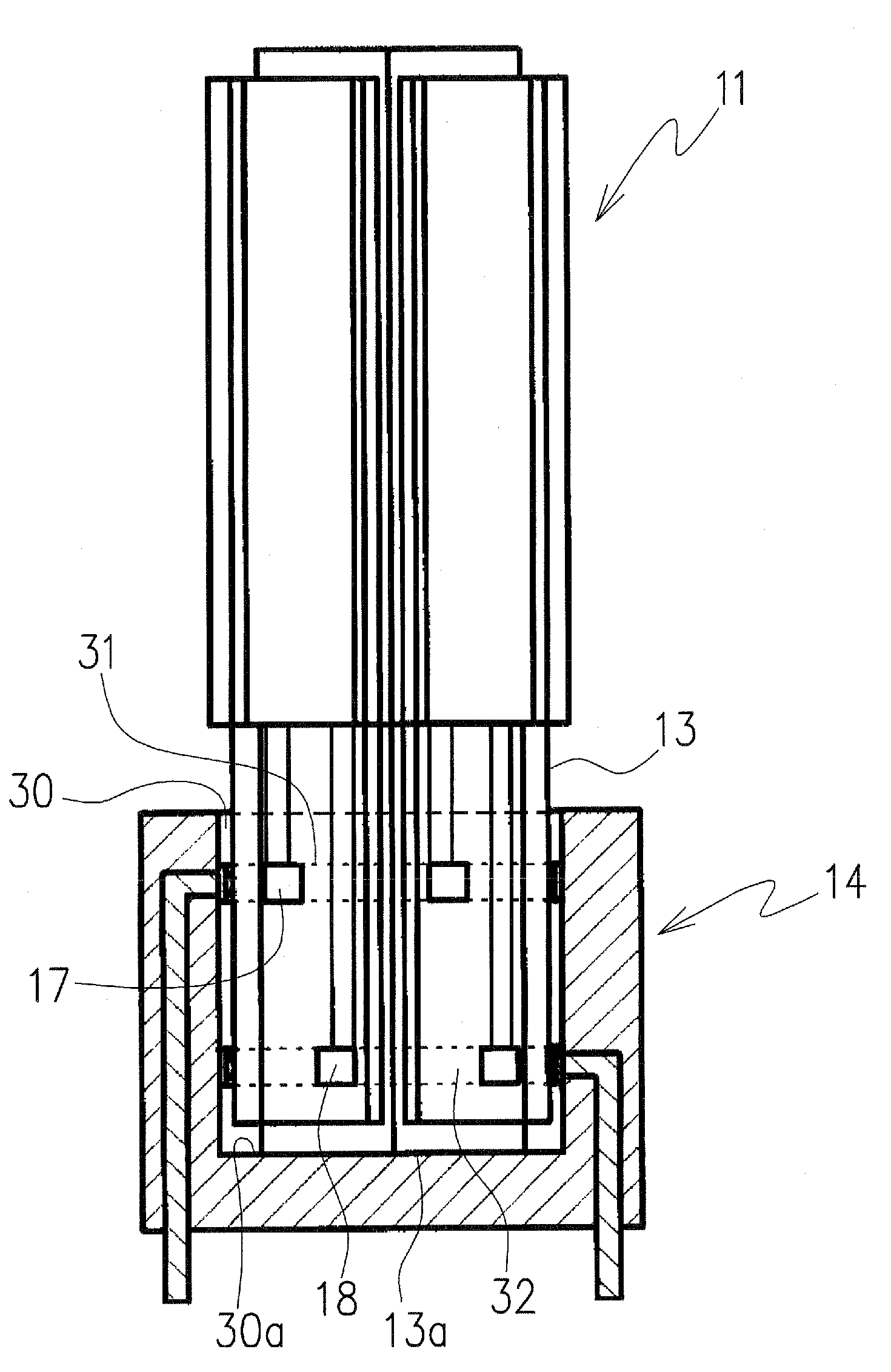
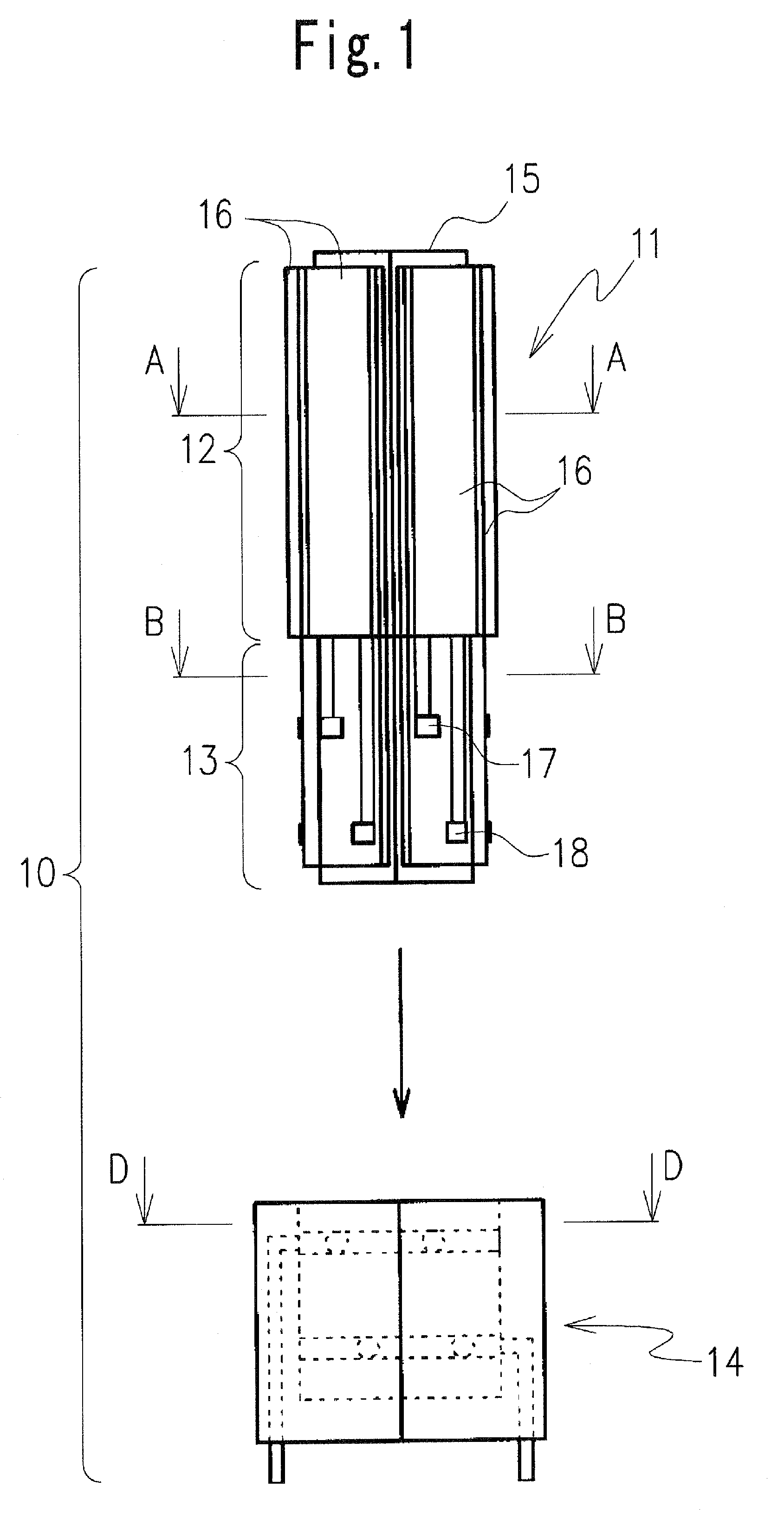
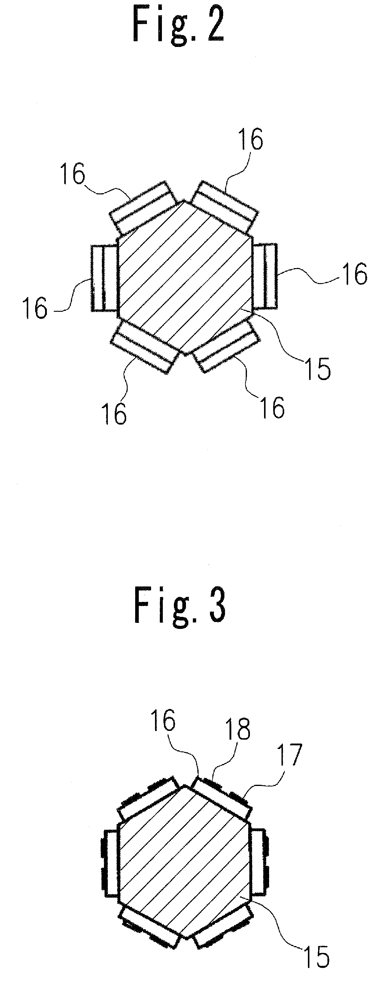
[0024]An LED lighting lamp according to one embodiment of the present invention includes a polygonal column-shaped supporting member 15 and a plurality of LED elements disposed on side surfaces of the supporting member, and terminal electrodes of the LED elements provided on one end of the supporting member can be detachably attachable in a socket. The LED lighting lamp is mounted on a motherboard by way of the socket or connected to an external socket directly linked to a power source. Thereby, it is possible to reduce cost of exchanging light sources. Hereinafter, specific embodiments of the present invention are described with reference to FIGS. 1 to 11.

[0025]One embodiment of LED lighting lamp according to the present invention is illustrated in FIGS. 1 to 3. As shown in FIG. 1, the LED lighting lamp 10 includes a lamp body 11 having a light emitting...


PUM


Abstract

The present invention is an LED lighting lamp which comprises a lamp body including a light emitting part in which a plurality of LED elements are arranged on each of side surfaces of a polygonal supporting member and a connection part which is provided at a different position from that of the light emitting part and is formed with a plurality of terminal electrodes electrically connected to the LED elements, and a socket in which the connection part of the lamp body is fitted and which has a pair of output terminals electrically connected to the terminal electrodes, and which is configured to enhance reliability and long-term stability and reduce a cost involved in exchanging a light source.

Description

TECHNICAL FIELD[0001]The present invention relates to an LED lighting lamp using a plurality of light emitting diode elements as a light source.BACKGROUND ART[0002]A fluorescent-lamp-shaped LED lamp in which a plurality of light emitting diodes instead of a fluorescent light source are attached to a ready-made-fluorescent-lamp lighting appliance is disclosed as an example of a conventional LED lighting lamp (for reference, see Patent Document 1). A vehicle-mounted-signal lamp fitting which uses a plurality of light emitting diodes as a light source is also known (for reference, see Patent Document 2). Each of the fluorescent-lamp-shaped LED lamp and the vehicle-mounted-signal lamp fitting in such conventional art usually has a structure in which a plurality of light emitting diodes 93 are mounted on one board 94, as shown in FIG. 12. For the board 94, a glass-epoxy-resinous board is usually used. The board 94 has an upper surface with conductive patterns printed on it to form a ligh...

Claims


Application Information

Patent Timeline
Patent Type & Authority Patents(United States)
IPC IPC(8): H01J61/30H01J61/00H01L33/56H01L33/62
CPCF21V19/001H01R33/94F21K9/135F21Y2101/02F21Y2111/005F21Y2111/007F21W2101/02H01L2224/48091H01L2224/45144F21K9/232F21Y2115/10F21Y2107/30F21Y2107/40F21S43/19F21S43/15F21W2107/10H01L2924/00014H01L2924/00
Inventor IMAI, SADATOKANAMORI, MASAYOSHI
Owner CITIZEN ELECTRONICS CO LTD
Why Eureka
Try Eureka