Eureka AIR delivers breakthrough ideas for toughest innovation challenges, trusted by R&D personnel around the world.

Backlight module and liquid crystal display device using same

a liquid crystal display and backlight module technology, applied in the field of backlight modules and liquid crystal display devices, can solve problems such as achieve the effects of preventing damage to light guide plates, reducing the thickness of backlight modules, and reducing manufacturing costs

Active Publication Date: 2015-10-01
SHENZHEN CHINA STAR OPTOELECTRONICS TECH CO LTD
View PDF2 Cites 1 Cited by
  • Summary
  • Abstract
  • Description
  • Claims
  • Application Information

AI Technical Summary

Benefits of technology

The present invention provides a backlight module and a liquid crystal display device using the backlight module. The bottom plate of the backplane is formed with an arc curved surface and the reflector plate is positioned on the arc curved surface to make the reflector plate in an arc curved shape. The reflector plate is directly supported on the two ends of the reflector plate, effectively reducing the thickness of the backlight module and preventing damage to the light guide plate due to friction caused by surface roughness of the bottom plate. This results in a thinner and longer-lasting backlight module. The efficiency of the present invention is that it provides a thinner and more cost-effective liquid crystal display device without compromising its performance.

Problems solved by technology

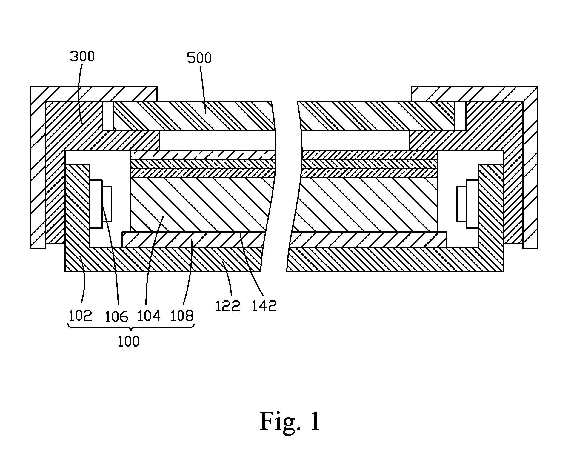
However, when the surface of the bottom plate 122 of the backplane 102 that faces the reflector plate 108 is not sufficiently smooth (such as having raised portions), the reflector plate 108 would be raised up thereby increasing friction between the reflector plate 108 and the light guide plate 104 and thus readily leading to damage of the light guide plate 104.

Method used


Image

  • Backlight module and liquid crystal display device using same
  • Backlight module and liquid crystal display device using same
  • Backlight module and liquid crystal display device using same

Examples


Embodiment Construction

[0033]To further expound the technical solution adopted in the present invention and the advantages thereof, a detailed description is given to a preferred embodiment of the present invention and the attached drawings.

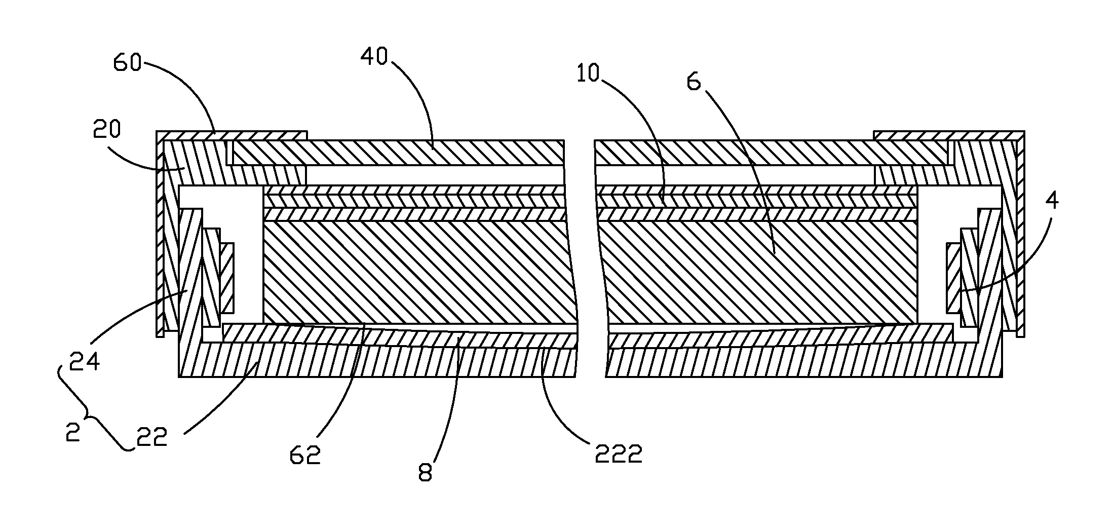
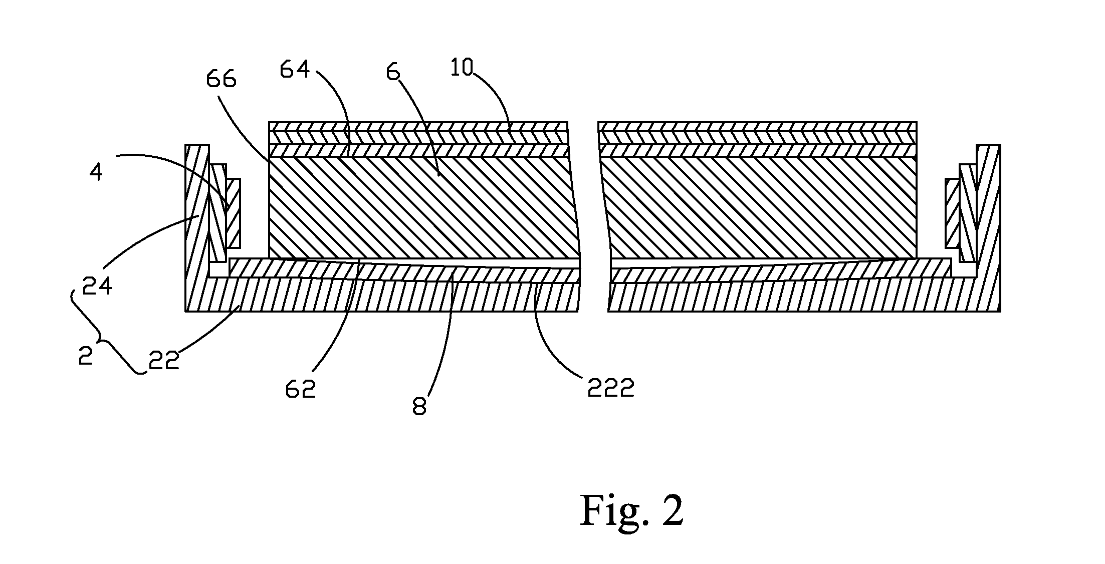
[0034]Referring to FIG. 2, the present invention provides a backlight module, which comprises: a backplane 2, a backlight source 4 arranged in the backplane 2, a light guide plate 6 arranged in the backplane 2, and a reflector plate 8 arranged between the backplane 2 and the light guide plate 6. The backplane 2 comprises a bottom plate 22 and a plurality of side plates 24 perpendicularly connected to the bottom plate 22. The bottom plate 22 has a surface that faces the light guide plate 6 and is an arc curved surface 222. The reflector plate 8 is positioned on the arc curved surface 222 and shows an arc curved configuration. The light guide plate 6 is supported on opposite ends of the reflector plate 8. Since the reflector plate 8 is configured in an arc curved shape, ...


PUM

PropertyMeasurementUnit
thicknessaaaaaaaaaa
frictionaaaaaaaaaa
surface roughnessaaaaaaaaaa

Abstract

The present invention provides a backlight module and a liquid crystal display device using the backlight module. The backlight module includes: a backplane (2), a backlight source (4) arranged in the backplane (2), a light guide plate (6) arranged in the backplane (2), and a reflector plate (8) arranged between the backplane (2) and the light guide plate (6). The backplane (2) includes a bottom plate (22) and a plurality of side plates (24) perpendicularly connected to the bottom plate (22). The bottom plate (22) has a surface that faces the light guide plate (6) and is an arc curved surface (222). The reflector plate (8) is positioned on the arc curved surface (222) and shows an arc curved configuration. The light guide plate (6) is supported on opposite ends of the reflector plate (8) to effectively reduce the thickness of the backlight module and not to be in complete contact with the reflector plate to thereby effectively prevent the occurrence of abrasion and wear of the light guide plate resulting from insufficient smoothness of the bottom plate of the backplane and effectively extend the lifespan of the backlight module.

Description

BACKGROUND OF THE INVENTION[0001]1. Field of the Invention[0002]The present invention relates to the field of liquid crystal displaying, and in particular to a backlight module and a liquid crystal display device using the backlight module.[0003]2. The Related Arts[0004]Liquid crystal displays have a variety of advantages, such as thin device body, low power consumption, and being free of radiation, and are thus widely used. Most of the liquid crystal displays that are currently available in the market are backlighting liquid crystal displays, which comprise a liquid crystal display panel and a backlight module. The operation principle of the liquid crystal display panel is that, with liquid crystal molecules interposed between two parallel glass substrates, a number of tiny vertical and horizontal electrical wires are arranged between the two glass substrates to selectively receive application of electricity thereto to control the rotation direction of the liquid crystal molecules ...

Claims


Application Information

Patent Timeline
Patent Type & Authority Applications(United States)
IPC IPC(8): G02F1/1333F21V8/00
CPCG02F1/133308G02B6/0055G02F2001/133314G02F2001/133317G02B6/0088G02F1/133314G02F1/133317
Inventor YU, GANG
Owner SHENZHEN CHINA STAR OPTOELECTRONICS TECH CO LTD
Why Eureka
Eureka Blog
Learn More