Optical detecting module and optical detector thereof

a technology of optical detection module and optical detector, which is applied in the field of optical detection module, can solve the problems of self-mixing in the resonance chamber failing, and achieve the effects of improving the sensibility of the optical detector, increasing the optical-electrical variation, and reducing the conversion cost of optical-electrical variation and electric signal

Inactive Publication Date: 2008-02-26
DARFON ELECTRONICS CORP
View PDF3 Cites 7 Cited by
  • Summary
  • Abstract
  • Description
  • Claims
  • Application Information

AI Technical Summary

Benefits of technology

[0010]The invention reduces the first angle θ between the laser beam and the measurement surface to improve a sensibility of the optical detector. Additionally, signal conversion cost between the optical-electrical variation and the electric signal is reduced via increasing optical-electrical variation in the resonance chamber.

Problems solved by technology

However, as shown in FIG. 1c, the first scattering beam 32 is not aimed at the resonance chamber, there is insufficient first scattering beam 32 traveling into the resonance chamber, and self-mixing in the resonance chamber fails.

Method used


Image

  • Optical detecting module and optical detector thereof
  • Optical detecting module and optical detector thereof
  • Optical detecting module and optical detector thereof

Examples


first embodiment

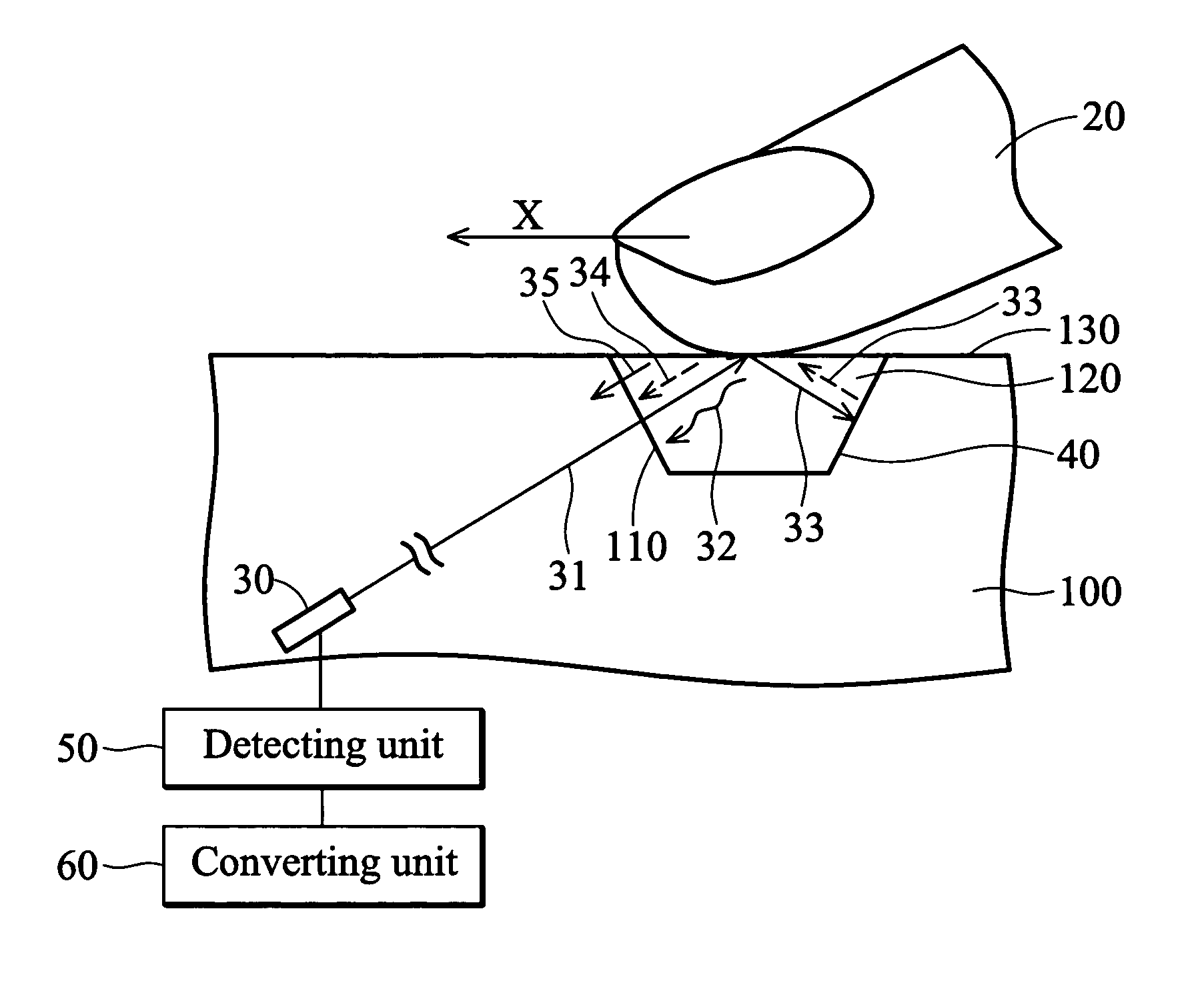
[0025]FIG. 2a shows the invention, which comprises a light source (laser diode) 30, a light guide 100, a detecting unit 50 and a converting unit 60. The light source 30 comprises a resonance chamber (not shown). The light guide 100 comprises a recess 120 comprising a first light emitting surface 110 and reflective portion 40. The first light emitting surface 110 and the reflective portion 40 are located on sidewalls of the recess 120. The detecting unit 50 is coupled to the light source 30. The converting unit 60 is coupled to the detecting unit 50.

[0026]The light source 30 emits a laser beam 31 toward an object 20. The laser beam 31 travels out of the light guide 100 from the first light emitting surface 110, contacts the object 20, and generates a first scattering beam 32 and a reflection beam 33. A part of the first scattering beam 32 travels into the resonance chamber. The reflection beam 33 is reflected by the reflective portion 40 to the object 20. The reflection beam 33 conta...

second embodiment

[0031]FIG. 3 shows the invention, wherein the laser beam 31, the first scattering beam 32, the reflection beam 33, the sub-reflection beam 35 and the second scattering beam 34 travel in the light guide 100. The laser beam 31 and the reflection beam 33 are emitted out of the light guide 100 through a second light emitting surface 112 (measurement surface 130) to contact the object 20. The recess 120 alters the light transmitting medium to reflect the reflective light 33. The reflective portion 40 is a simple planar surface located on a sidewall of the recess 120 or a planar surface coated with light reflective material.

third embodiment

[0032]FIG. 4a shows the invention, wherein the light guide 100 is a polyhedron. The reflective portion 40 is located on a surface of the light guide 100. The laser beam 31, the first scattering beam 32, the reflection beam 33, the sub-reflection beam 35 and the second scattering beam 34 travel in the light guide 100. The laser beam 31 and the reflection beam 33 are emitted out of the light guide 100 through a second light emitting surface 112 (measurement surface 130) to contact the object 20. The reflective portion 40 is a planar surface located on a sidewall of the recess 120 or a planar surface coated with light reflective material.

[0033]FIG. 4b shows a modified form of the third embodiment, wherein the reflective portion 40 is a curved surface. The reflective portion 40 can also be in other shapes to reflect light.


PUM


Abstract

An optical detector measuring a movement of an object in a space on a measurement axis comprises a light source, a reflective portion, a detection unit and a converting unit. The light source comprises a resonance chamber, the light source emitting a laser beam toward the object, the laser beam contacting the object and generating a first scattering beam and a reflection beam, wherein a part of the first scattering beam enters the resonance chamber. The reflective portion reflects the reflection beam toward the object, the reflection beam re-contacting the object and generating a second scattering beam and a sub-reflection beam, wherein a part of the second scattering beam and the sub-reflection beam enter the resonance chamber. The detection unit measures an optical-electrical variation in the resonance chamber to generate an electric signal. The converting unit converts the electric signal to a movement on the measurement axis in the space.

Description

BACKGROUND OF THE INVENTION[0001]1. Field of the Invention[0002]The invention relates to an optical detector, and in particular to an optical detector with decreases manufacturing costs.[0003]2. Description of the Related Art[0004]FIG. 1a shows a conventional optical detector, wherein a laser diode 30 emits a laser beam 31 toward an object 20 moving on a measurement surface 10. The laser beam 31 contacts the object 20 and generates a reflection beam 33 and a first scattering beam 32. The object 20 moves on an x-axis, and Doppler frequency shifts the first scattering beam 32. When the first scattering beam 32 backs to a resonance chamber (not shown) in the laser diode 30, a self-mixing effect occurs in the resonance chamber to generate an optical-electrical variation. A movement on the x-axis of the object 20 and a click motion thereof are measured via measuring the optical-electrical variation by a photodiode.[0005]A measurement effect of the conventional optical detector is related...

Claims


Application Information

Patent Timeline
Patent Type & Authority Patents(United States)
IPC IPC(8): G01B9/02G01P3/36G09G5/00
CPCG01P3/366G06F3/0421
Inventor LIAO, PIN-CHIENMA, KUO-TONG
Owner DARFON ELECTRONICS CORP
Why Eureka
Try Eureka