Temperature control device

a temperature control device and temperature technology, applied in the direction of temperature control using electric means, indirect heat exchangers, lighting and heating apparatus, etc., can solve the problems of inability to quickly change the temperature inside the temperature adjustment unit is not easy to change, etc., to achieve the effect of reducing the amount of work and quick placemen

Inactive Publication Date: 2008-12-25
TOKYO ELECTRON LTD +1
View PDF7 Cites 26 Cited by
  • Summary
  • Abstract
  • Description
  • Claims
  • Application Information

AI Technical Summary

Benefits of technology

[0037]With open loop control, the optimal setting of the gain, the period of time control is to continue, and the target value, will depend on the controlled object. Thus, by fixing these parameters from the start in the temperature control device, open loop control may not be able to be performed on the controlled object. By providing the adjustment support means, means 13 can reduce the amount of work performed when a user of the temperature control device applies these parameters in response to the controlled object.
[0038]In an aspect of the invention of means 14, the adjustment means can adjust the downstream side flow dimensions of each of the heating pathway, the cooling pathway, and the bypass pathway. The manipulating means prevents the path dimensions of the heating pathway and the cooling pathway that are adjusted by the adjustment means from reaching zero when the temperature inside and/or near the temperature adjustment unit is in a steady state.
[0039]When the supply of fluid from the heating pathway and the cooling pathway to the temperature adjustment unit is prohibited, a temperature gradient will be created between the downstream side of the adjustment mean...

Problems solved by technology

The aforementioned temperature control device requires a long period of time in order to change to the desired temperature of a controlled object.
Because of th...

Method used


Image

  • Temperature control device
  • Temperature control device
  • Temperature control device

Examples


first embodiment

[0054]A first embodiment of the temperature control device according to the present invention will be described below with reference to the drawings.

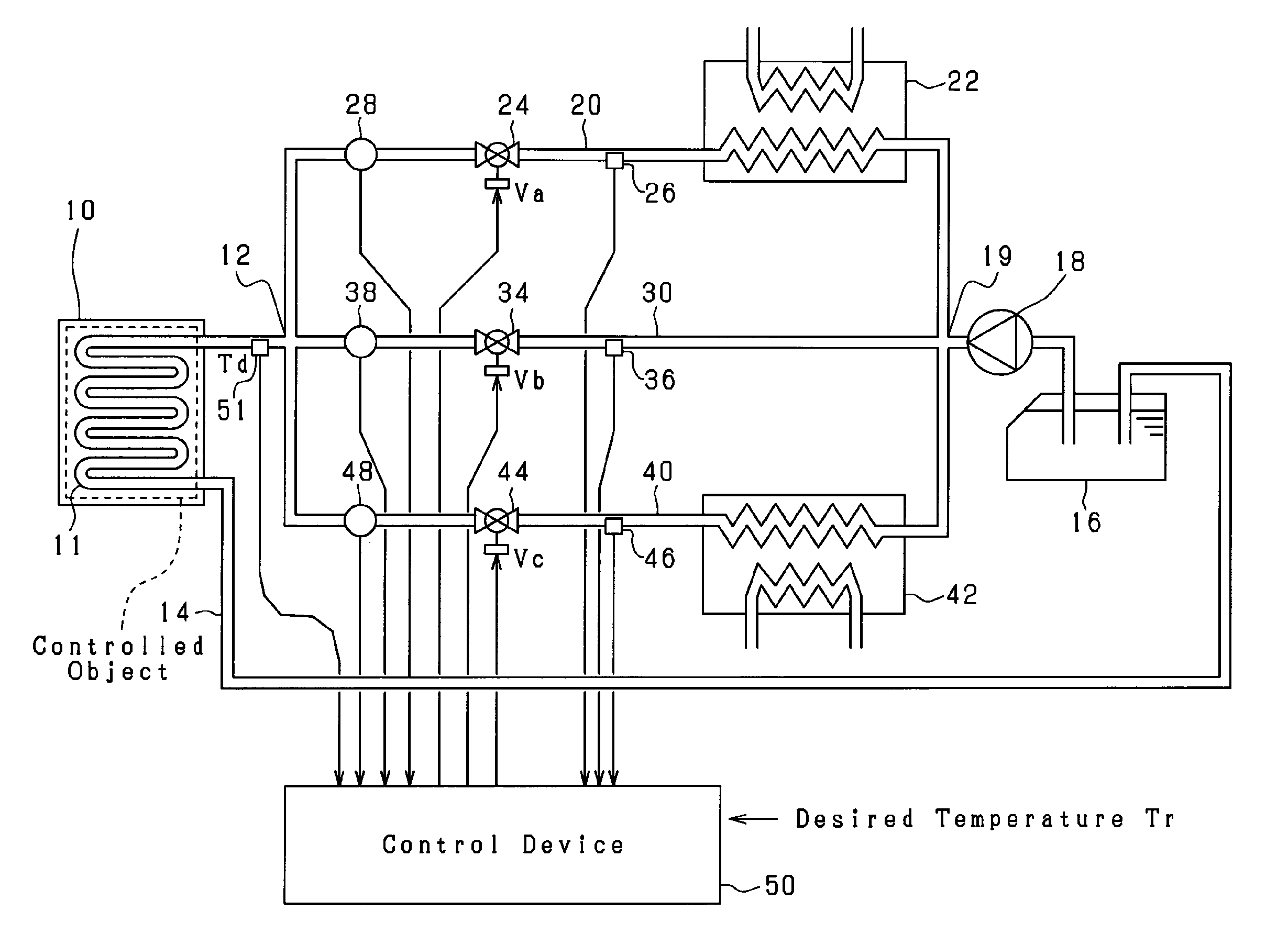
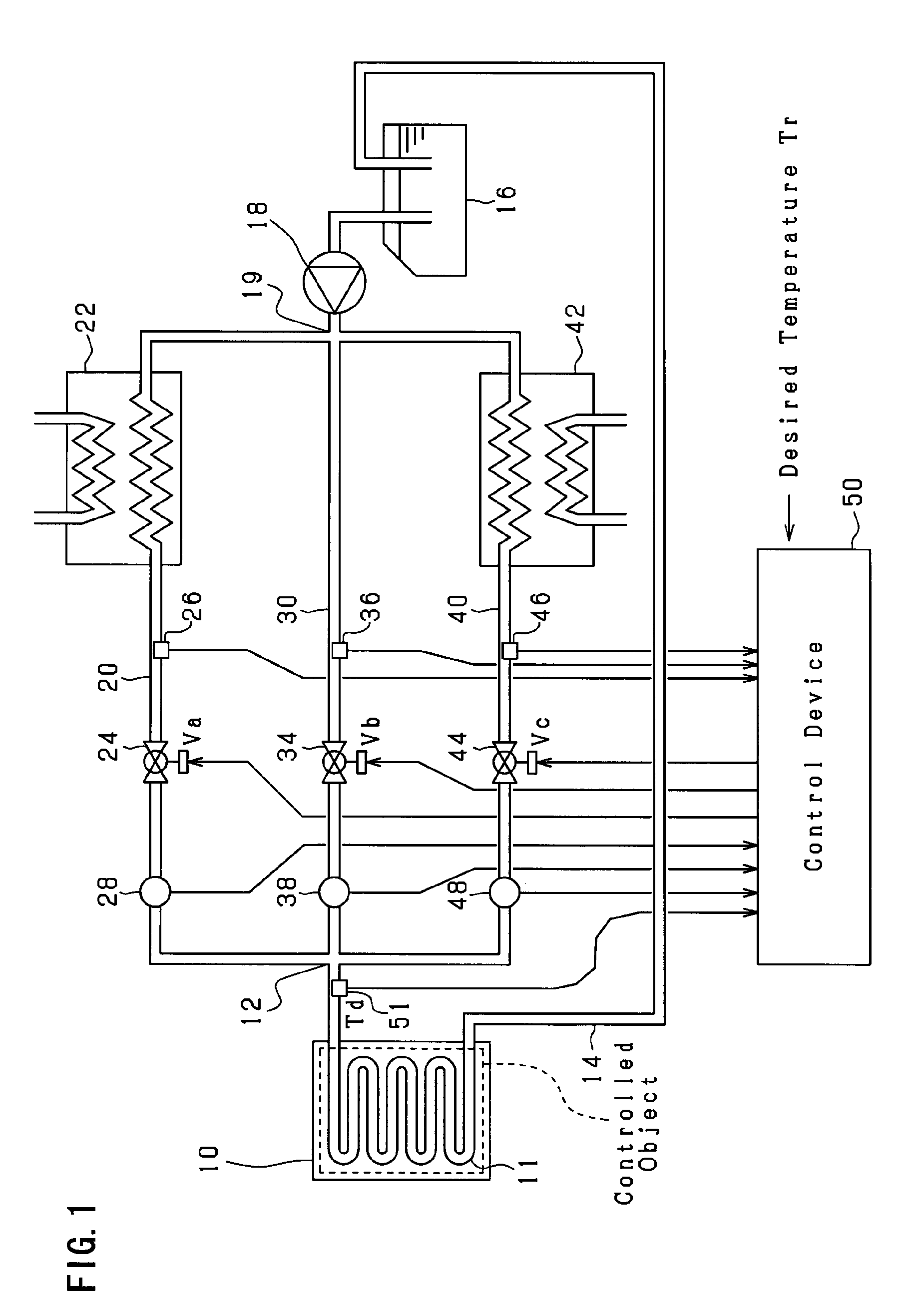
[0055]FIG. 1 shows the overall construction of the temperature control device according to the present embodiment.

[0056]The illustrated temperature control device is employed in, for example, processes / manufacturing steps in the bioengineering field and the chemical engineering field, bioengineering / chemical experimentation, semiconductor manufacturing processes, manufacturing processes for precision machinery. The temperature control device comprises a temperature adjustment plate 10. The temperature adjustment plate 10 is a plate shaped member that is capable of supporting a controlled object from below by mounting the controlled object on top thereof, and exchanges heat energy with the controlled object. More specifically, a pathway (temperature adjustment unit 11) is provided in the interior of the temperature adjustment plate 10, a...

second embodiment

[0109]A second embodiment will be described below with reference to the drawings that are focused on the points that differ from the first embodiment.

[0110]FIG. 8 shows the overall construction of the temperature control device according to the present embodiment. As shown in FIG. 8, in the present embodiment, a effusion pathway 60 that effuses the fluid inside the cooling pathway 20 to the discharge pathway 14 is connected between the cooling temperature sensor 26 and the cooling valve 24 along the cooling pathway 20. In addition, a effusion pathway 62 that effuses the fluid inside the heating pathway 40 to the discharge pathway 14 is connected between the heating temperature sensor 46 and the heating valve 44 along the heating pathway 40.

[0111]These effusion pathways 60 and 62 are sufficiently smaller than the path dimensions of either of the cooling pathway 20 and the heating pathway 40. This is in order to allow a minute amount of fluid to be effused from the cooling pathway 20 ...

third embodiment

[0116]A third embodiment will be described below with reference to the drawings that are focused on the points that differ from the first embodiment.

[0117]FIG. 9 shows the relationship between the basic manipulating variable MB according to the present embodiment and the ratio of opening Va, Vb and Vc of the cooling valve 24, the bypass valve 34, and the heating valve 44. As shown in FIG. 9, in the present embodiment, the ratio of opening Va of the cooling valve 24 and the ratio of opening Vc of the heating valve 44 are set so as not to be in a completely closed state. In other words, the ratio of opening Va of the cooling valve 24 will monotonically decrease in accordance with an increase in the basic manipulating variable MB when the basic manipulating variable MB is less than zero, and will be at the minimum ratio (>0) when the basic manipulating variable MB is zero or more. In addition, the ratio of opening Vc of the heating valve 44 will monotonically increase in accordance wit...


PUM


Abstract

A temperature control device controls the temperature of a controlled object by circulating a fluid in a temperature adjustment unit arranged near the controlled object. The temperature control device comprises a heating pathway that heats and circulates the fluid in the temperature adjustment unit, a cooling pathway that cools and circulates the fluid in the temperature adjustment unit, a bypass pathway that does not pass the fluid through the heating pathway and cooling pathway, but circulates the fluid in the temperature adjustment unit, and adjustment means that adjust a flow ratio of the fluid that is supplied from the heating pathway, cooling pathway, and bypass pathway to the temperature adjustment unit via a confluence unit that combines these flows. The adjustment means are provided on a downstream side of each of the heating pathway, the cooling pathway, and the bypass pathway and on the upstream side of the confluence unit.

Description

FIELD OF THE INVENTION[0001]The present invention relates to a temperature control device that controls the temperature of a controlled object by circulating a fluid in a temperature adjustment unit arranged near the controlled object.BACKGROUND ART[0002]FIG. 12 shows this type of temperature control device. Fluid inside a storage tank 100 is drawn by a pump 102, and is discharged to a heating unit 104. The heating unit 104 is comprised of a heater, and is capable of heating the fluid to be supplied to a temperature adjustment unit 106. The fluid that has passed through the temperature adjustment unit 106 will be supplied to a cooling unit 108. The cooling unit 108 is capable of cooling the fluid to be discharged to the storage tank 100.[0003]The temperature adjustment unit 106 is capable of supporting a controlled object, and the temperature of the controlled object that is supported by the temperature adjustment unit 106 will be controlled by adjusting the temperature of the fluid...

Claims


Application Information

Patent Timeline
IPC IPC(8): F28D15/00
CPCG05D23/19G05D23/02
Inventor NAGASEKI, KAZUYAKOBAYASHI, YOSHIYUKIMURAKAMI, KOICHINONAKA, RYOSUDOH, YOSHIHISAITAFUJI, HIROSHIKOKUBO, NORIO
Owner TOKYO ELECTRON LTD
Why Eureka
Try Eureka