Rotating Electrical Machine

Inactive Publication Date: 2008-12-25
HITACHI LTD
View PDF5 Cites 35 Cited by
  • Summary
  • Abstract
  • Description
  • Claims
  • Application Information

AI Technical Summary

Benefits of technology

[0023]The present invention provides a rotating electrical machine with superior output performance.

Problems solved by technology

However, the literature does not include any mention of how the characteristics may be improved.

Method used


Image

  • Rotating Electrical Machine
  • Rotating Electrical Machine
  • Rotating Electrical Machine

Examples


first embodiment

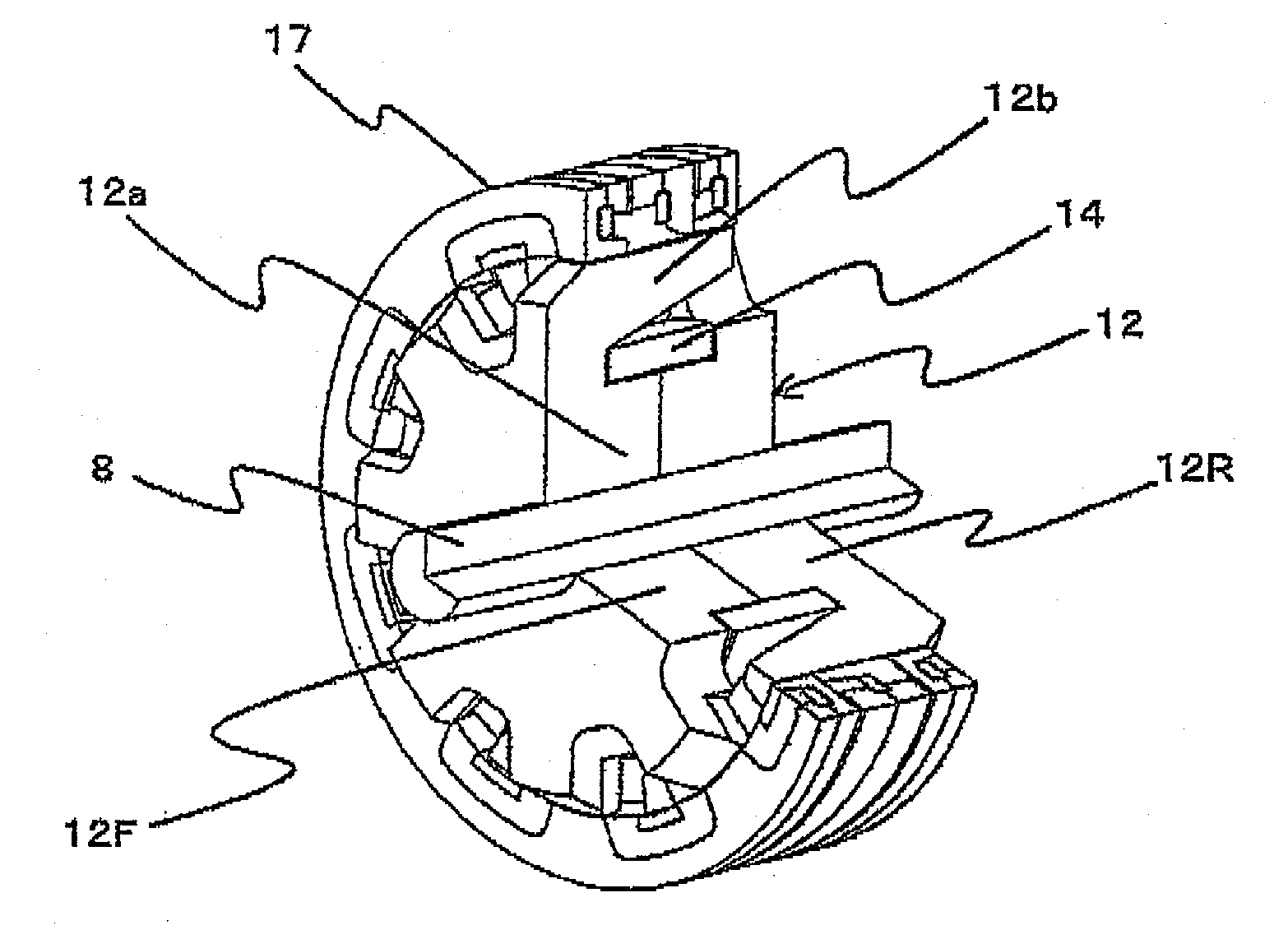
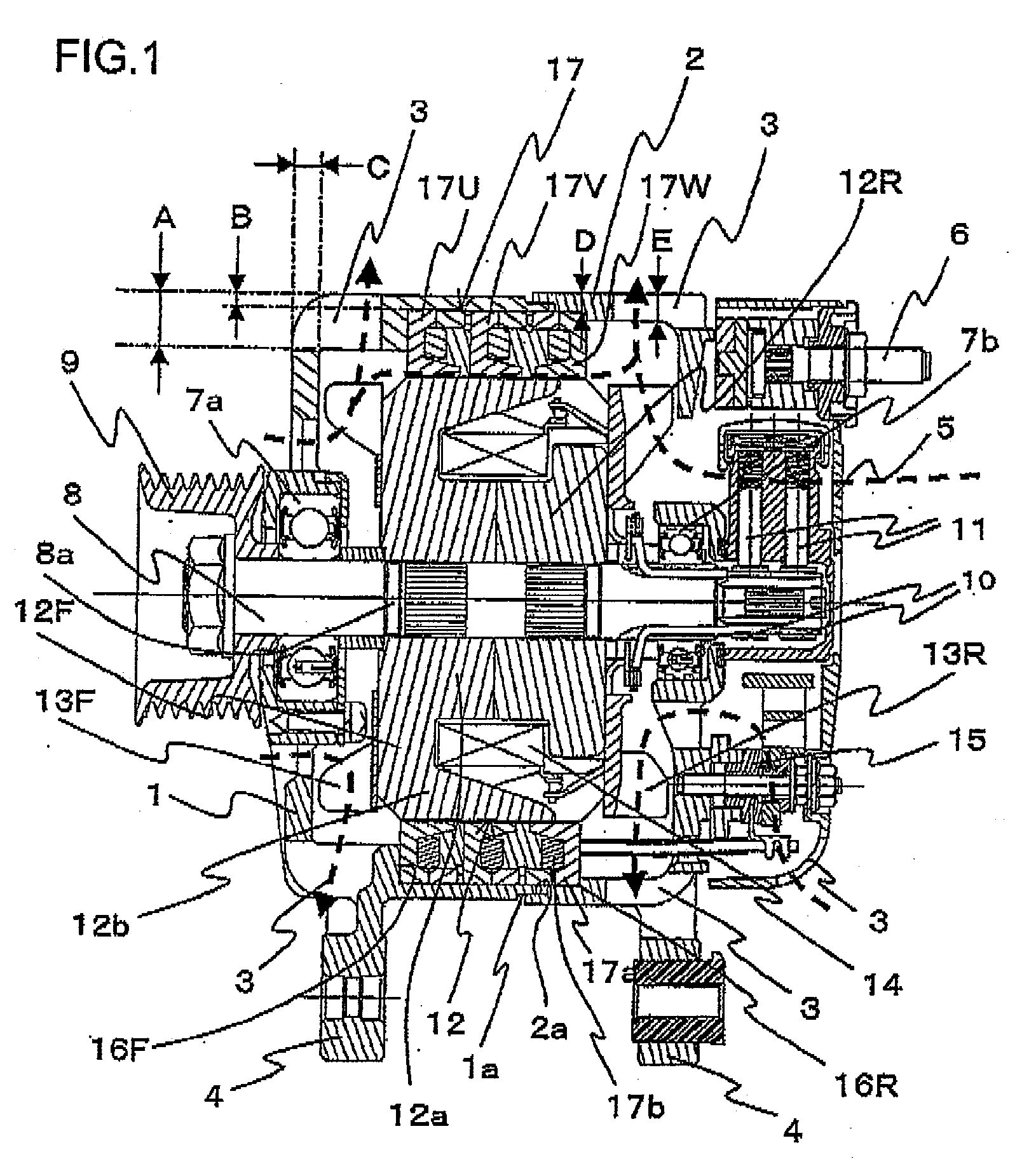
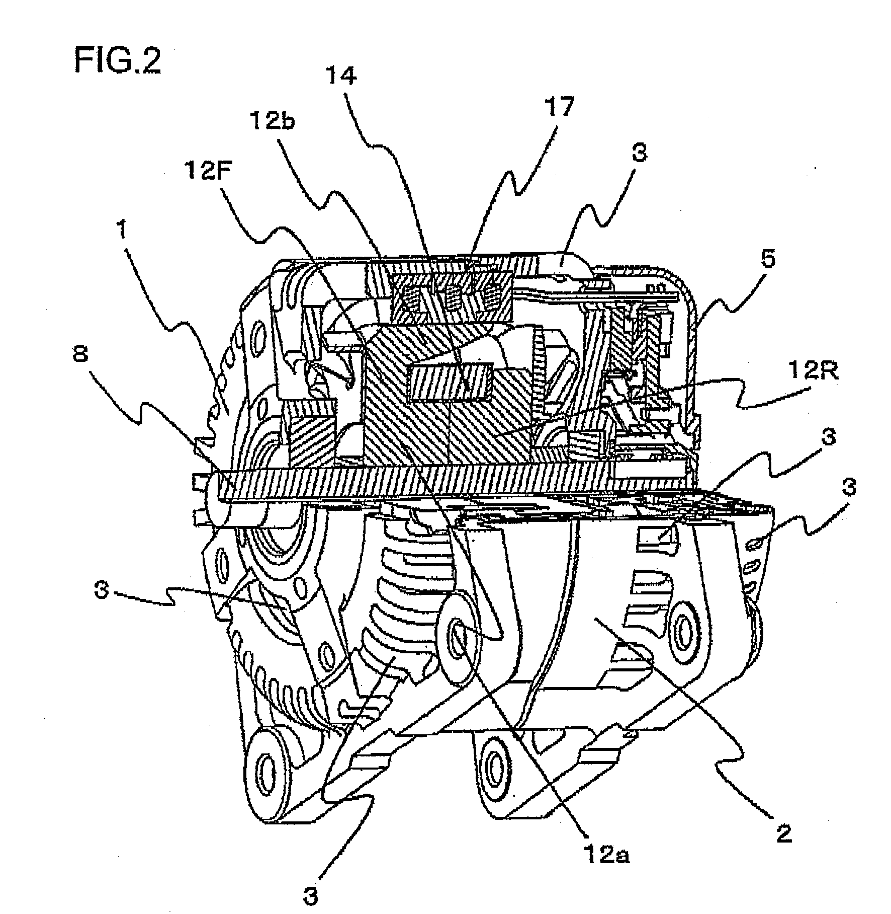
[0040]In reference to FIGS. 1 through 7, the alternator for vehicle achieved in an embodiment of the rotating electrical machine according to the present invention is described. FIG. 1 is a sectional view taken through a side of the alternator for vehicle. FIG. 2 is a perspective showing the alternator for vehicle in a partial sectional view. FIG. 3 is a perspective of a rotor and a stator in a partial sectional view. FIG. 4 is a perspective of the rotor. FIG. 5A is a perspective showing the stator alone in a partial sectional view. FIG. 5B shows the stator viewed from the inner circumferential side. FIG. 6 is a perspective showing the phase stators. FIG. 7A is a perspective of a phase stator corresponding to a single phase and FIG. 7B is a perspective showing various parts in FIG. 7A.

[0041]The alternator for vehicle achieved in the embodiment in FIG. 1 includes a front bracket 1 disposed on the left side in the figure and a rear bracket 2 disposed on the right side in the figure. T...

second embodiment

[0098]As illustrated in FIG. 7, the stator core component members 174 and 175 assume a substantially unvarying thickness over their outer circumferential surfaces except for where the projecting portions 1744 and 1754 and the recessed portions 1745 and 1755, at which the stator core component members are to be fitted together, are present. The following is a description of the flow of magnetic flux generated at the rotor 12 in the rotating electrical machine assuming this structure.

[0099]FIG. 8 shows the stator core component member 175, one of its stator core magnetic poles 1752, the stator core component member 174, one of its stator core magnetic poles 1742 and part of the stator coil 173.

[0100]In the first embodiment, magnetic fluxes alternately assuming N polarity and S polarity are generated at the rotor claw poles 12b extending from the front-side rotor member 12F and the rear-side rotor member 12R and these magnetic fluxes interlink with the stator claw poles 1742 and 1752. ...

third embodiment

[0121]FIG. 13 shows a stator claw pole 1752 achieved in the third embodiment of the present invention in a sectional view similar to that presented in FIG. 11B taken through the central area A-A along the axial direction.

[0122]Magnetic theory indicates that the quantity of the air-gap flux ØL corresponding to the reactance described in reference to the second embodiment is in proportion to the gap distance Lg and also in reverse proportion to the sectional area Sg of the magnetic core facing the gap.

[0123]Accordingly, the thickness of the stator claw pole 1752 in FIG. 13 at the surface facing opposite the stator coil 173 is adjusted over two stages, Lc1 and Lc2, with the smaller thickness Lc2 assumed at the front end portion 1752a of the claw pole. As a result, the stator claw pole 1752 is formed with the front end portion 1752a thereof assuming a smaller sectional area Sg2 than the sectional area Sg1 assumed on the base side of the stator claw pole 1752. It is to be noted that sinc...


PUM


Abstract

Stator claw poles are disposed at a stator core at a position facing opposite a rotor so as to alternately range from the two sides along the axial direction. With a plurality of magnetic poles thus formed, the distance by which the gap between the front end portions of the stator claw poles and the stator outer circumference ranges is increased, which, in turn, reduces the reactance guided to a stator coil. It is ensured that the magnetic reluctance manifesting between the front end portions of the stator claw poles and an enclosing member that holds the stator core, facing opposite the centers of the claw poles along the circumferential direction, is greater than the magnetic reluctance manifesting between the front portions and the stator core enclosing member facing opposite the front end portions.

Description

CROSS-REFERENCE TO RELATED APPLICATION[0001]The present application relates to subject matters described in a co-pending patent application Ser. No. 11 / 950,595 filed on Dec. 5, 2007 entitled “ROTATING ELECTRICAL MACHINE”.INCORPORATION BY REFERENCE[0002]The disclosure of the following priority application is herein incorporated by reference:[0003]Japanese Patent Application No. 2007-160847 filed Jun. 19, 2007BACKGROUND OF THE INVENTION[0004]1. Field of the Invention[0005]The present invention relates to a rotating electrical machine such as an electric generator or a motor.[0006]2. Description of Related Art[0007]A stator in an electric generator, a motor or the like includes a stator core having formed therein a plurality of slots opening toward the rotational axis center and disposed side-by-side along the circumferential direction and a plurality of stator coils wound through the individual slots.[0008]The rotating electrical machine assuming such a structure cannot be manufacture...

Claims


Application Information

Patent Timeline
IPC IPC(8): H02K1/06
CPCH02K1/145H02K1/243
Inventor ISHIKAWA, TOSHIOYABUKI, MINORUISHIKAWA, YOSHIHISATAHARA, KAZUO
Owner HITACHI LTD
Why Eureka
Try Eureka