Luminaire with Louver Members

a technology of luminaires and louvers, which is applied in outdoor lighting, fixed installations, lighting and heating apparatus, etc., can solve the problems of low ratio between the light emitted by the lamp and the light that is effectively used for illuminating the ground, and light pollution, so as to achieve the effect of improving efficiency

Inactive Publication Date: 2008-12-25
KONINKLIJKE PHILIPS ELECTRONICS NV
View PDF9 Cites 8 Cited by
  • Summary
  • Abstract
  • Description
  • Claims
  • Application Information

AI Technical Summary

Benefits of technology

[0007]It is an object of the invention to provide a reflec...

Problems solved by technology

This leads to light pollution.
However, a large part of the light is absorbed by the top surfaces of the annular louver members.
As ...

Method used


Image

  • Luminaire with Louver Members
  • Luminaire with Louver Members
  • Luminaire with Louver Members

Examples


Embodiment Construction

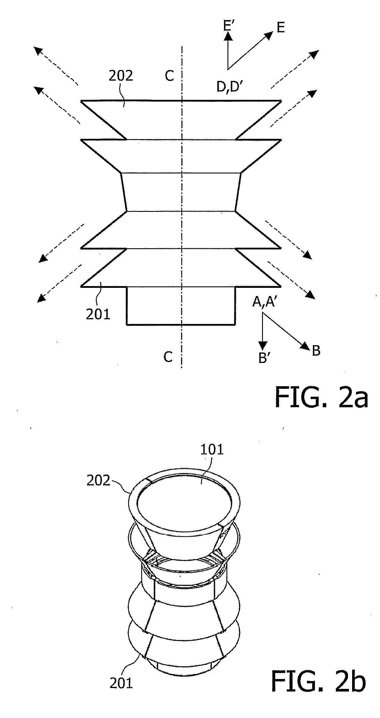
[0019]A reflector in accordance with the invention is depicted in FIGS. 2a and 2b, where FIG. 2a is a cross section and FIG. 2b a perspective view of said reflector. This reflector comprises a cavity 101 and, arranged around said cavity, a first annular louver member 201 and a second annular louver member 202. The first and second annular louver member 201 and 202 are symmetrical with respect to the axis of revolution CC. However, the first and / or second annular louver member 201 and / or 202 may be asymmetrical. An annular louver member is a louver member which is at least in part a surface of revolution.

[0020]The direction of the first annular louver member 201 is represented by the vector A′B′, whereas the direction of the second annular louver member 202 is represented by the vector D′E′. The directions of the first and second annular louver members 201 and 202 are opposite. As a consequence, a reflector in accordance with the invention leads to a controlled emission of light in t...


PUM


Abstract

The invention relates to a reflector for a luminaire. The reflector comprises a cavity (101) for receiving a lamp intended to emit light and, located around said cavity, a first annular louver member (201) arranged in a first direction and a second annular louver member (202) arranged in a second, opposite direction.

Description

FIELD OF THE INVENTION[0001]The present invention relates to a reflector for a luminaire, said reflector comprising annular louver members. It also relates to a luminaire comprising such a reflector.[0002]The present invention is particularly relevant for lighting, in particular outdoor lighting.BACKGROUND OF THE INVENTION[0003]Patent application EP 1 074 787 describes a reflector for a luminaire. This luminaire is intended for outdoor lighting, such as illumination of squares or other public or private areas. Such a reflector is shown in FIGS. 1a and 1b, where FIG. 1a is a cross section and FIG. 1b a perspective view of said reflector. It comprises a cavity 101 for receiving a lamp, and, around said cavity, annular louver members 102. The annular louver members 102 are arranged in a downward direction, which means that light passing through the annular louver members is mainly directed downwardly, with an angle that depends on the slopes of the annular louver members 102. The main ...

Claims


Application Information

Patent Timeline
IPC IPC(8): F21V7/00F21V11/02
CPCF21V9/08F21V11/02F21V13/10F21W2131/10F21W2131/107F21W2131/109F21S8/088F21V7/0008F21V29/15
Inventor LAC, CORINNEMARKOWSKI, ARTURDE VRIES, GERT-JAN BAUCOBEMBRIDGE, MATHEW LEEJURGIELAJTIS, GRZEGORZ
Owner KONINKLIJKE PHILIPS ELECTRONICS NV
Why Eureka
Try Eureka