

Shutter Assembly
- Summary
- Abstract
- Description
- Claims
- Application Information
AI Technical Summary
Benefits of technology
Problems solved by technology
Method used
Image

Examples
Embodiment Construction
[0047]Hereinafter, one preferred embodiment of a shutter assembly according to the present invention will be described, with reference to the attached drawings. Firstly described is a configuration of an optical adapter to which the shutter assembly is mounted.
[0048]Firstly given is description of a configuration of an SC optical adapter.
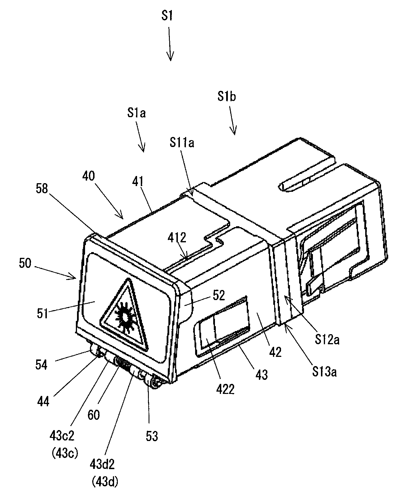
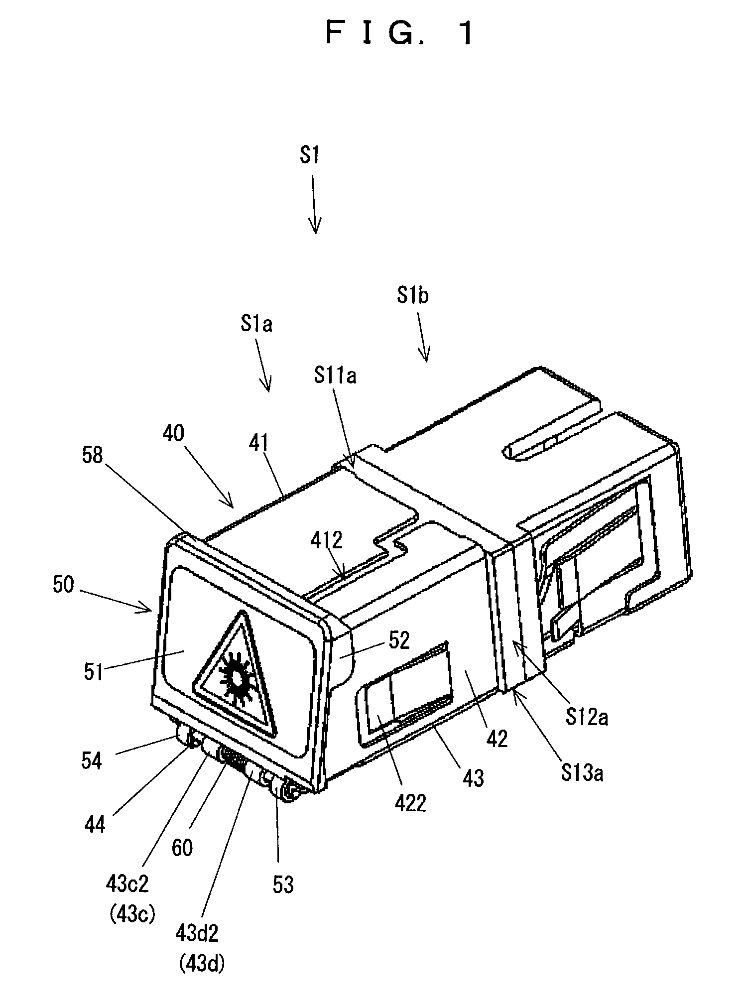
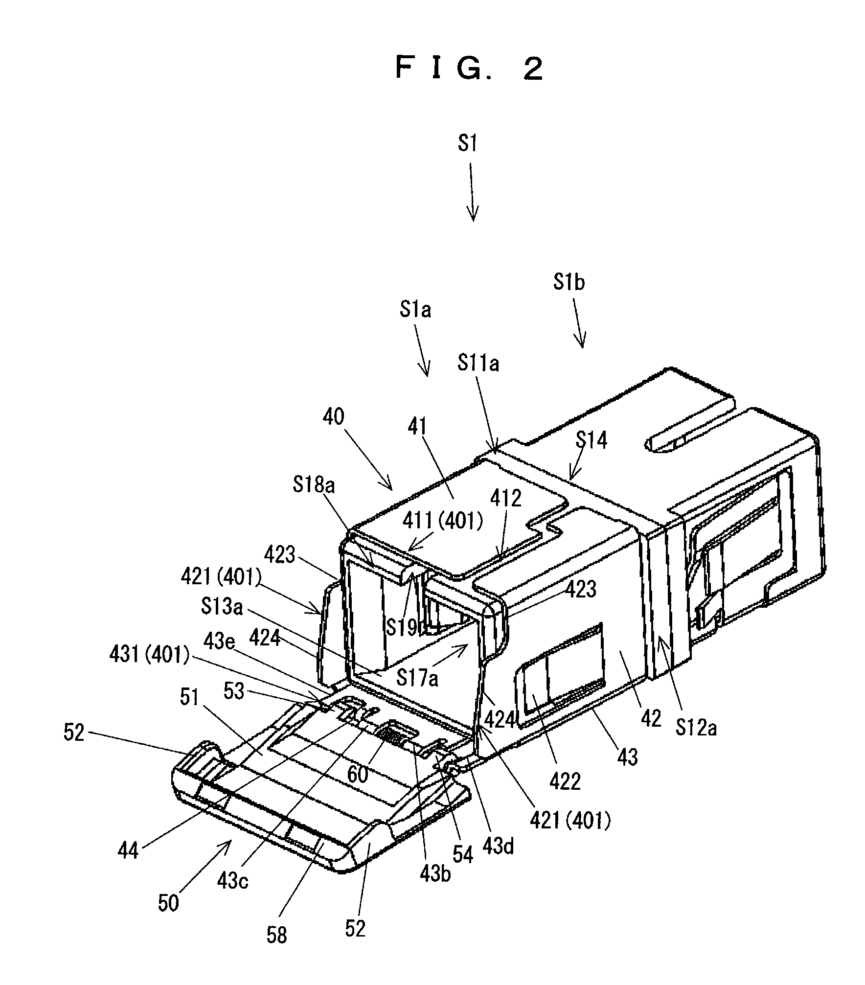
[0049]FIG. 10 is a perspective view of the SC optical adapter, and FIG. 11 is a perspective cross-sectional view of the SC optical adapter shown in FIG. 10, taken along its axial-line direction.
[0050]The SC optical adapter S1 is configured so that, as shown in FIGS. 10 and 11, a first optical cable S3 with an SC optical connector S2 provided on at least a first end side thereof is detachably coupled therewith.
[0051]In the present embodiment, the SC optical adapter S1 includes a first adapter housing S1a with which the first optical cable S3 with the optical connector S2 is coupled, and a second adapter housing S1b with which a second optical cable (...
PUM
 Abstract
Description
Claims
Application Information