Managing spool bearing load using variable area flow nozzle

a technology of variable area flow nozzle and bearing load, which is applied in the direction of machines/engines, stators, liquid fuel engines, etc., can solve the problems of large bearing thrust loads that are substantially higher, not actively managed bearing load in response, etc., and achieve the effect of changing the exit area of the fan nozzl

Active Publication Date: 2008-12-25
RTX CORP
View PDF3 Cites 214 Cited by
  • Summary
  • Abstract
  • Description
  • Claims
  • Application Information

AI Technical Summary

Benefits of technology

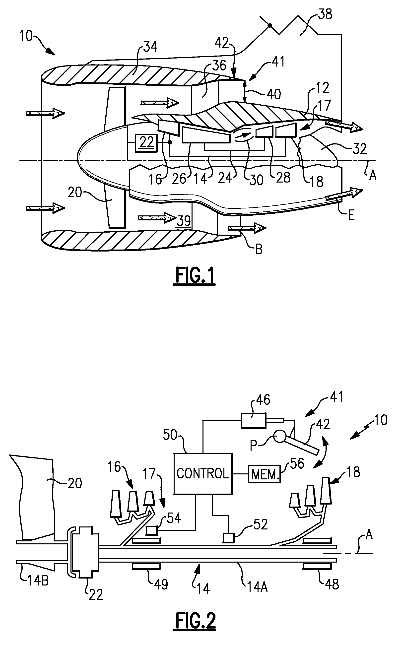
[0005]A turbine engine provides a spool supporting a turbine. The spool is arranged in an engine core and supported on bearings, which includes a thrust bearing. The engine core is covered by a core nacelle. A fan is arranged upstream from the core nacelle and is coupled to the spool. A fan nacelle surrounds the fan and core nacelle and provides a bypass flow path that includes a fan nozzle exit area. A flow control device is adapted to effectively change the fan nozzle exit area. A controller is programmed to monitor the thrust bearing and command the flow control device in response to an undesired load on the thrust bearing. Effectively changing the fan nozzle exit area with the flow control device actively manages the bearing thrust load to desired levels.

Problems solved by technology

The bearing loading is not actively managed in response to any measured bearing load.
These types of geared turbofan engines can result in large bearing thrust loads that are substantially higher than non-geared turbofan engines.

Method used


Image

  • Managing spool bearing load using variable area flow nozzle
  • Managing spool bearing load using variable area flow nozzle

Examples


Embodiment Construction

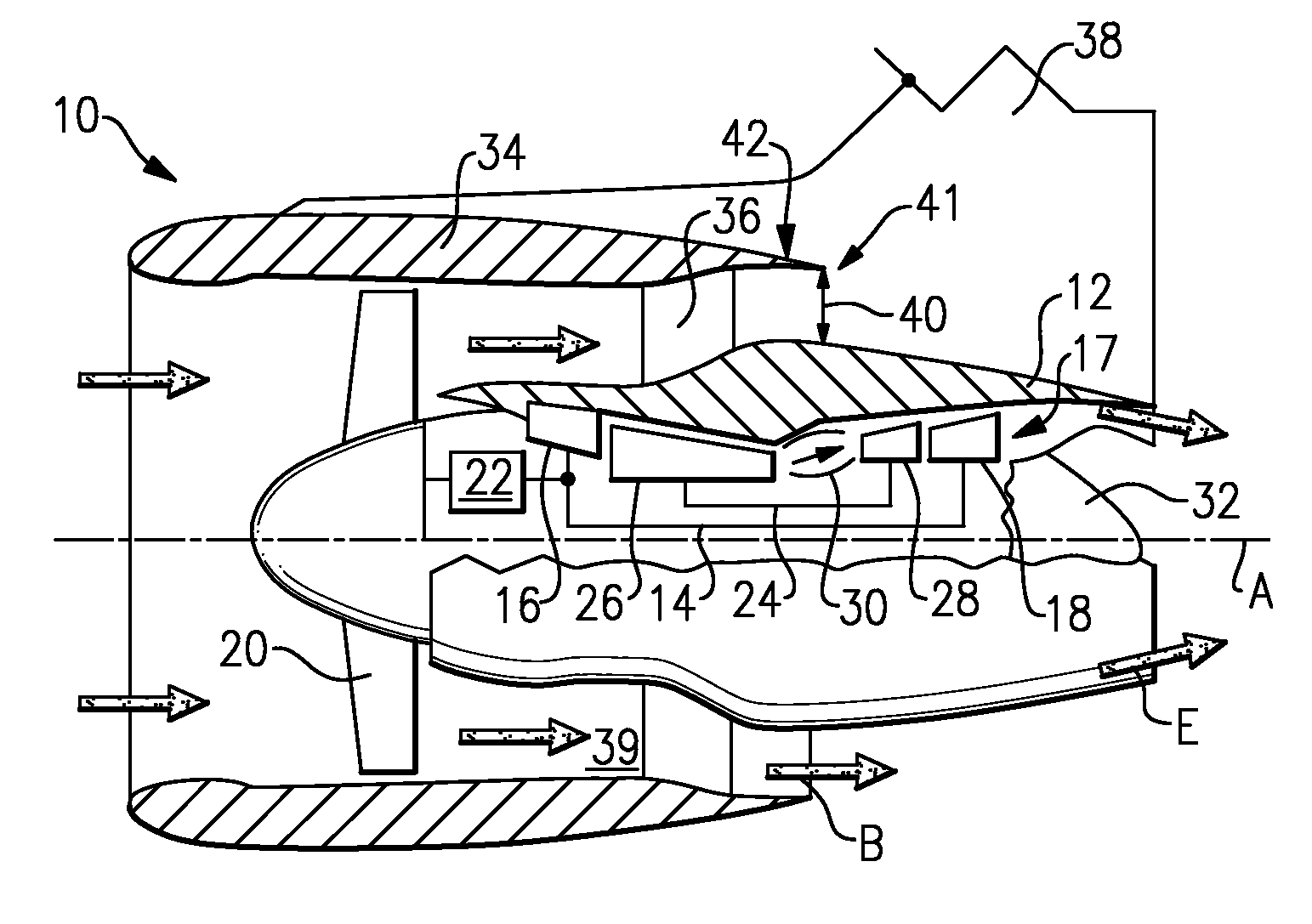
[0009]A geared turbofan engine 10 is shown in FIG. 1. A pylon 38 supports the engine 10 on an aircraft. The engine 10 includes a core nacelle 12 that houses a low spool 14 and high spool 24 rotatable about an axis A. The low spool 14 supports a low pressure compressor 16 and low pressure turbine 18. In the example, the low spool 14 drives a fan 20 through a gear train 22. The high spool 24 supports a high pressure compressor 26 and high pressure turbine 28. A combustor 30 is arranged between the high pressure compressor 26 and high pressure turbine 28. Compressed air from compressors 16, 26 mixes with fuel from the combustor 30 and the combustion gases are expanded in turbines 18, 28.

[0010]In the examples shown, the engine 10 is a high bypass turbofan arrangement. In one example, the bypass ratio is greater than 10:1, and the fan diameter is substantially larger than the diameter of the low pressure compressor 16. The low pressure turbine 18 has a pressure ratio that is greater than...


PUM


Abstract

A turbine engine provides a spool supporting a turbine. The spool is arranged in a core nacelle and includes a thrust bearing. A fan is arranged upstream from the core nacelle and is coupled to the spool. A fan nacelle surrounds the fan and core nacelle and provides a bypass flow path that includes a fan nozzle exit area. A flow control device is adapted to effectively change the fan nozzle exit area. A controller is programmed to monitor the thrust bearing and command the flow control device in response to an undesired load on the thrust bearing. Effectively changing the fan nozzle exit area with the flow control device actively manages the bearing thrust load to desired levels.

Description

BACKGROUND OF THE INVENTION[0001]This application relates to turbine engine bearings. More particularly, the application relates to bearing load management in a turbofan turbine engine, for example.[0002]One typical turbofan engine includes high and low spools. A fan is coupled to the low spool, which also supports a low pressure compressor and low pressure turbine, for example. In one example, a high pressure compressor and high pressure turbine are coupled to the high spool. The low and high spools are supported within a housing provided by an engine core using bearings. In one example, engine core is covered by a core nacelle.[0003]Some turbofan engines include a bearing load sensor in communication with a thrust bearing. The axial loads at the thrust bearing are recorded for maintenance purposes, for example. The bearing loading is not actively managed in response to any measured bearing load.[0004]Some turbofan engines include a gear train arranged between one portion of the lo...

Claims


Application Information

Patent Timeline
Patent Type & Authority Applications(United States)
IPC IPC(8): F03B11/06
CPCF01D21/04F01D25/16F02K1/12F02K1/70F05D2270/114F05D2270/304F05D2270/30
Inventor GRABOWSKI, ZBIGNIEW M.WINTER, MICHAEL
Owner RTX CORP
Why Eureka
Try Eureka