Emission control system internal to a boiler

a technology of emission control system and boiler, which is applied in the direction of emission prevention, separation process, and flue gas purification components, etc., can solve the problems of affecting overall performance, forming unburnt hydrocarbons, and reducing nosub>x, so as to reduce noxious emissions, reduce back pressure, and achieve no heat loss

Inactive Publication Date: 2008-12-25
CATALYTIC SOLUTIONS INC
View PDF10 Cites 21 Cited by
  • Summary
  • Abstract
  • Description
  • Claims
  • Application Information

AI Technical Summary

Benefits of technology

This patent describes a new way to use catalysts in power plants to reduce harmful emissions. By placing the catalyst within the boiler itself, it helps decrease back pressure and minimizes energy loss during the process. Additionally, this setup eliminates the risk of losing valuable heat from the exhaust gases. Overall, this method improves efficiency and reduces pollution levels in power plant operations.

Problems solved by technology

The technical problem addressed in this patent text needs to be identified by a senior R&D personnel who has read it through.

Method used


Image

  • Emission control system internal to a boiler
  • Emission control system internal to a boiler
  • Emission control system internal to a boiler

Examples


Embodiment Construction

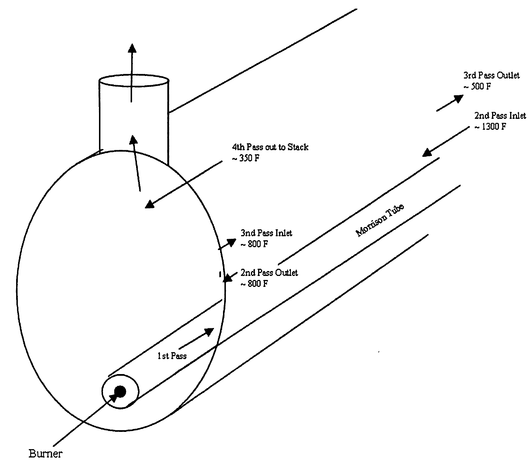
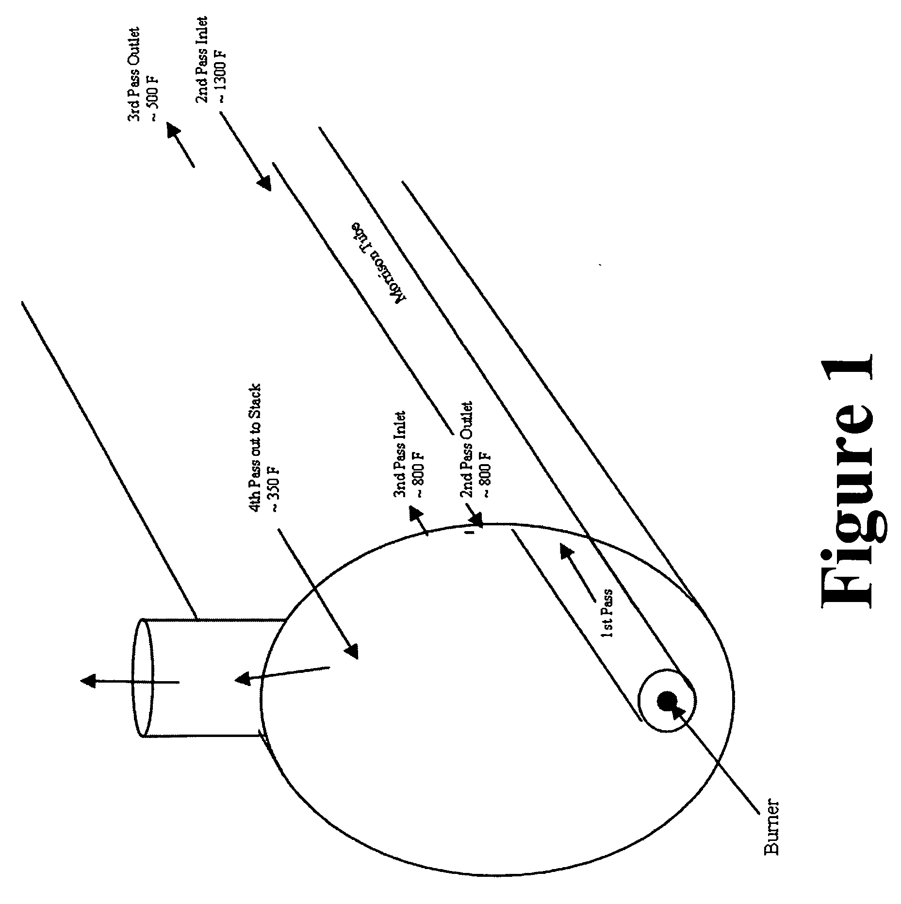
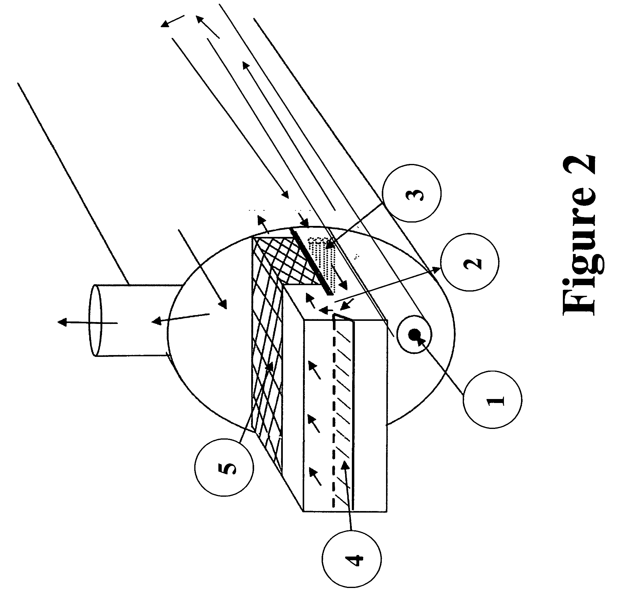
[0030]The invention is an emission control system comprising a boiler within which is a reactor within which is any SCR catalyst for NOx reduction and / or any CO catalyst for CO reduction.

[0031]In one embodiment, hot flue gas from the burner is mixed with a suitable reducing agent, then flows through the SCR catalytic bed which is inside the boiler. NOx in the flue gas reacts with the reducing agent in the reactor, and is converted to harmless nitrogen and water. The reducing agent may be introduced (e.g., without limitation, injected) upstream of the SCR catalyst.

[0032]In another embodiment, an ethanol SCR catalyst can be placed in the temperature window of about 715—about 815° F. inside the fire tube boiler. An ethanol SCR catalyst is defined to mean a SCR catalyst which uses ethanol as a reducing agent. In a fire tube boiler, such a temperature can be realized, for example, between the end of the second pass and the beginning of the 3 pass. The ethanol SCR catalyst along with the ...


PUM

PropertyMeasurementUnit
Temperatureaaaaaaaaaa

Abstract

This invention is an emission control system wherein the boiler hosts a reactor which contains one or more catalysts for the purpose of reducing NOx and/or CO in the emissions. The reactor containing the NOx/CO catalysts may be placed at a place where the temperature is in the range of 300-1000° F. The hot flue gas can be diverted using control dampers and blended with colder flue gas inside the boiler to achieve the desired flue gas temperature for the selected catalyst. NOx is removed by the SCR catalyst inside the boiler upon injecting a suitable reducing agent (e.g. ammonia, or hydrocarbons). The CO and NOx catalysts may be used in any order. The emission control system is an integral part of the boiler, and the existing capabilities of the boiler to recover the heat from flue gas, after the catalyst layers, is utilized such that the overall boiler efficiency remains high.

Description


Claims


Application Information

Patent Timeline
Owner CATALYTIC SOLUTIONS INC
Why Eureka
Try Eureka