System and method for distributed thermoelectric heating and cooling

a distributed thermoelectric heating and cooling technology, applied in the direction of refrigeration components, machine operation modes, light and heating apparatuses, etc., can solve the problems of slow response time of the system, significant energy waste, and approach also suffers from energy losses

Active Publication Date: 2009-01-01
GENTHERM INC
View PDF110 Cites 123 Cited by
  • Summary
  • Abstract
  • Description
  • Claims
  • Application Information

AI Technical Summary

Benefits of technology

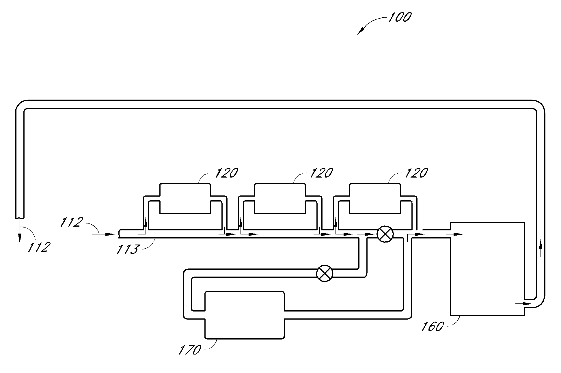
[0022]In certain embodiments, the network further comprises a central processing unit. Flow of the first working fluid through the one or more conduits to each first heat exchanger is adjustable in certain embodiments by at least one valve responsive to signals from the central processing unit. In certain embodiments, the network further comprises at least one sensor in electrical communication with the central processing unit. The central processing unit is configured to receive at least one signal from the at least one sensor. The at least one signal of certain embodiments is indicative of at least one condition within a volume to be locally heated or cooled. The at least one condition can be selected from the group consisting of: ambient temperature, local surface temperature, radiant loads, humidity, occupant number, occupant weight, occupant clothing thickness, and occupant location.
[0023]In certain embodiments, the network further comprises a thermal storage reservoir fluidically coupled to the one or more conduits. In certain such embodiments, the thermal storage reservoir is configured to store thermal power during peak generation events and to return thermal power to the first working fluid according to need. In certain embodiments, the network further comprises an intermediate heat exchanger fluidically coupled to the one or more conduits. In certain such embodiments, the intermediate heat exchanger is in thermal communication with a target object to be cooled or heated.
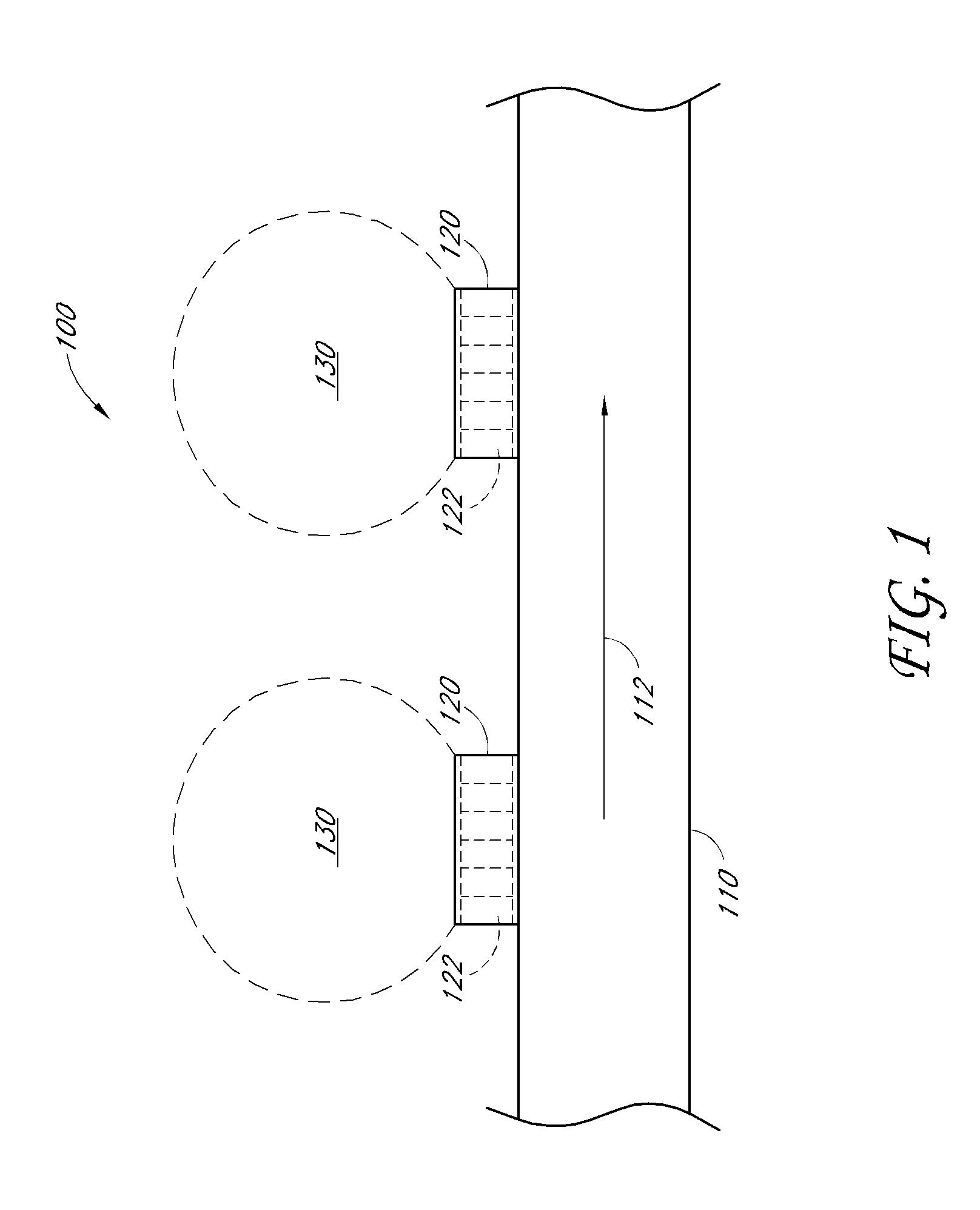
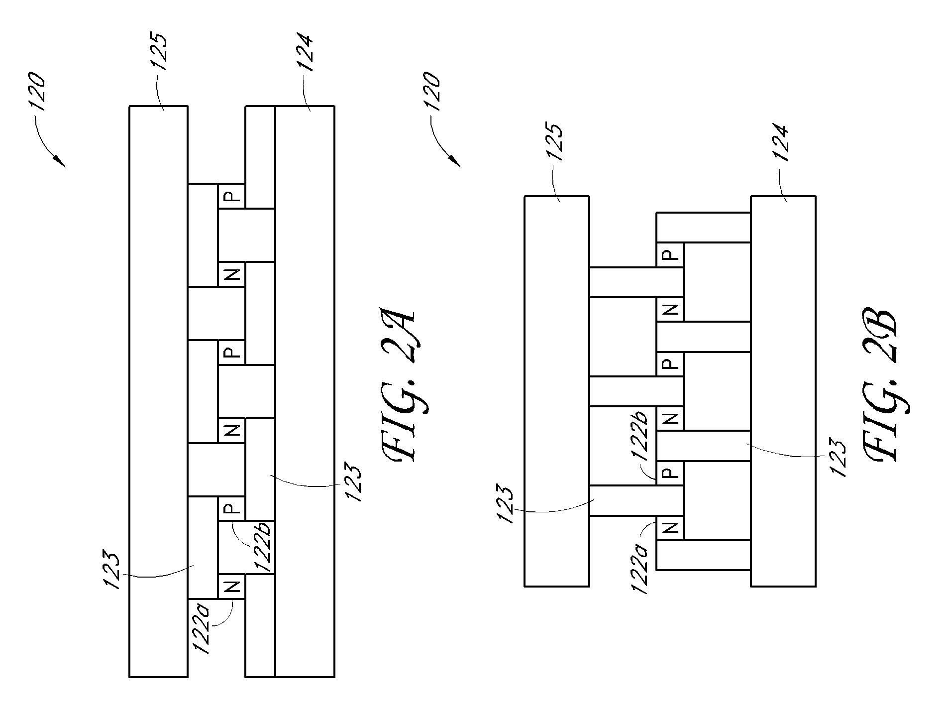
[0024]In certain embodiments, a network of distributed thermoelectric assemblies is provided for heating, cooling, or both heating and cooling localized portions of a passenger compartment of a vehicle. The network comprises a plurality of thermoelectric assemblies. Each thermoelectric assembly has a first side and a second side. Each thermoelectric assembly is selectively operable either to heat a region corresponding to the thermoelectric assembly by transferring heat from a first working fluid to the region corresponding to the thermoelectric assembly or to cool the region corresponding to the thermoelectric assembly by transferring heat from the region corresponding to the thermoelectric assembly to the first working fluid. Each thermoelectric assembly is operable independently from operation of other thermoelectric assemblies of the plurality of thermoelectric assemblies. Each thermoele

Problems solved by technology

Heating and cooling of objects other than the targets results in significant energy waste, and slower response time for the system.
This approach also suffers from the energy losses described above.
The system is subject to significant losses as only a fraction of the thermal power developed by the central system reaches the target objects as the majority of the thermal capacity is wasted conditioning walls, ducting, ceilings, windows and furniture.
Centralized heating and cooling systems with rotating mechanical parts tend to be noisy, and are subject to seal and other mechanical failures.
Building heating and cooling is also provided by smaller, localized units, however such units utilize compressors for cooling which are noisy, vibrate, and utilize mechanical parts subject to failure, use ozone depleting refrigerants, and an additional unit is required for heating.
The use of thermoelectric devices for these applications has been limited as they suffer from poor efficiency and use too much thermoelectric material to provide the needed capacity within cost constraints.
In addition, the cooling devices of such syste

Method used


Image

  • System and method for distributed thermoelectric heating and cooling
  • System and method for distributed thermoelectric heating and cooling
  • System and method for distributed thermoelectric heating and cooling

Examples


Embodiment Construction

[0046]A distributed system described by Elliot et al. (U.S. Patent Application Publication No. US2007 / 0000255, published Jan. 4, 2007, “Autonomous Air-Conditioning Module Intended Particularly for the Thermal Treatment of an Area of a Vehicle Cabin”) heats and cools automobile passenger cabin air by circulating the air through localized and autonomously controlled thermoelectric devices. The modules have air intake and exhaust features to force the air through the Peltier devices. The system, however, is limited in capacity as the result of several factors.

[0047]Firstly, the thermoelectric module described by Elliot operates by recirculating cabin air through a thermoelectric device. The thermal capacity of such a device is significantly limited according to the relatively low heat capacity of the working fluids used compared certain embodiments described herein.

[0048]Secondly, the thermoelectric device described by Elliot is inefficient compared to certain embodiments described her...


PUM


Abstract

A thermoelectric system and method provides distributed localized heating, cooling, or both heating and cooling. The thermoelectric system includes a plurality of thermoelectric assemblies. Each thermoelectric assembly comprises a plurality of thermoelectric elements, and each thermoelectric assembly is in thermal communication with a first working fluid and in thermal communication with a region corresponding to the thermoelectric assembly. Each thermoelectric assembly is selectively operable either to heat the region corresponding to the thermoelectric assembly by transferring heat from the first working fluid to the region corresponding to the thermoelectric assembly or to cool the region corresponding to the thermoelectric assembly by transferring heat from the region corresponding to the thermoelectric assembly to the first working fluid. Each thermoelectric assembly is operable independently from operation of other thermoelectric assemblies of the plurality of thermoelectric assemblies.

Description

CROSS-REFERENCE TO RELATED APPLICATIONS[0001]This application claims the benefit of U.S. Provisional Application No. 60 / 940,372, filed May 25, 2007, which is incorporated in its entirety by reference herein, and U.S. Provisional Application No. 60 / 953,157, filed Jul. 31, 2007, which is incorporated in its entirety by reference herein.BACKGROUND[0002]1. Field of the Invention[0003]The present application relates generally to the field of ventilating, heating, and cooling systems for the creation and distribution of comfort air and the thermal management of sensitive systems for which temperature control is important.[0004]2. Description of the Related Art[0005]Heating and cooling to achieve comfort and to manage the temperature of critical systems and equipment is primarily accomplished through centralized systems. In these systems, hot and cold working fluids are used to provide temperature control for target objects within comparatively large volumes and surrounding structures. The...

Claims


Application Information

Patent Timeline
IPC IPC(8): F25B21/02
CPCB60H1/00271B60H1/00478B60H1/00492F25B2400/24F25B2321/0251F25B2321/0252F25B21/04B60N2/5614B60H2001/00942B60H2001/00949B60H1/00278B60H1/00285B60H1/00885B60H1/034
Inventor BELL, LON E.LAGRANDEUR, JOHN
Owner GENTHERM INC
Why Eureka
Try Eureka