Brake rotor

a technology of brake rotor and rotor, which is applied in the direction of braking disc, noise/vibration control, braking elements, etc., can solve the problems of long-standing problems such as warranty costs, loss of future sales, and vibration of brakes and the noise resulting from

Inactive Publication Date: 2009-01-01
AKEBONO CORP (NORTH AMERICA)
View PDF35 Cites 41 Cited by
  • Summary
  • Abstract
  • Description
  • Claims
  • Application Information

AI Technical Summary

Benefits of technology

[0006]The present invention seeks to improve on prior brake systems and particularly vibration and noise thereof by providing an improved rotor design having tangential stiffening features located about the rotor axis. In one aspect, the present invention provides a cast brake rotor. The rotor includes a pair of spaced apart plates defining an outer circumference and a rotational axis. The rotor also includes a fin pattern that is located between the spaced apart plates, wherein the fin pattern includes a plurality of cast fins located between the plates and at least one tangentially oriented arcuate cast fin spaced apart from the plurality of cast fins and having an outer wall that extends at least 30° about the rotor (e.g. greater than about 90°). In another aspect, the present invention provides a cast brake rotor. The rotor includes a pair of spaced apart plates defining an outer circumference and a rotational axis. The rotor also includes a fin pattern that is asymmetrical about the rotational axis and is located between the spaced apart plates. The fin pattern includes a plurality of radially aligned cast fins located between the plates, and optionally an odd number of tangentially oriented arcuate cast fins having an outer wall that extends at least 30 about the rotor (e.g. greater than about 90°).

Problems solved by technology

Brake vibration and resulting noise therefrom has long been a common problem for brake suppliers and vehicle manufacturers.
This vibration and noise is a source of customer dissatisfaction resulting in warranty costs and loss of future sales.

Method used


Image

  • Brake rotor
  • Brake rotor
  • Brake rotor

Examples


Embodiment Construction

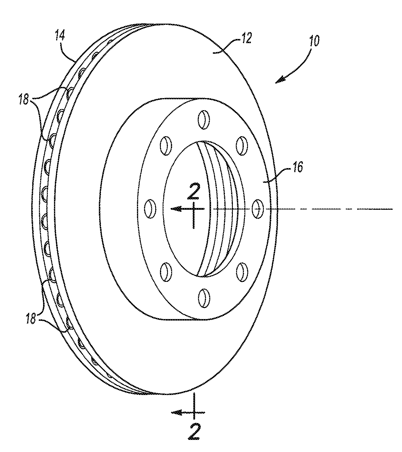
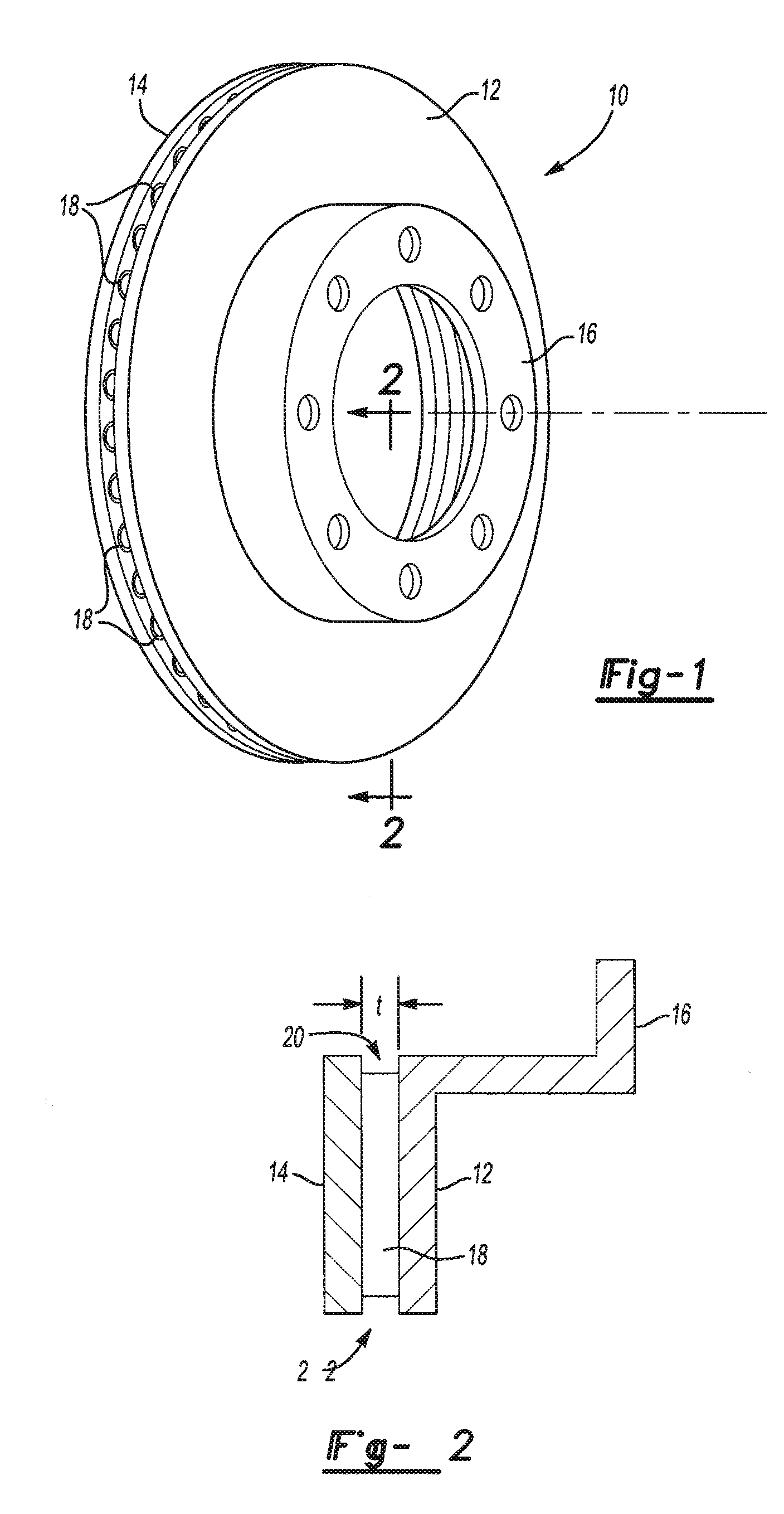
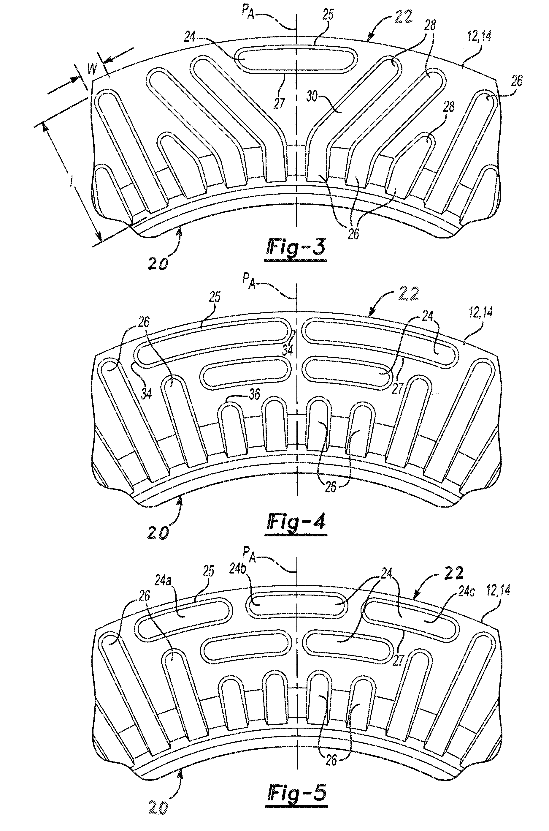
[0012]The present invention is directed to a cast brake rotor that includes a pair of spaced apart plates defining an outer circumference and a rotational axis. A fin pattern is located between the spaced apart plates including a plurality of cast fins located between the plates, and at least one tangentially oriented arcuate cast fin spaced apart from the plurality of cast fins and having an outer wall that extends at least 30° (e.g., at least about 90°, at least about 135°, at least about 180°, or even at least about 270°) about the rotor. The at least one tangentially oriented arcurate cast fin generally will have an outer wall that is spaced inwardly from the outer circumference of the rotor toward the rotational axis. Though other configurations are possible, the plurality of cast fins may include at least one radially oriented fin and at least one tangentially orientated arcurate cast fin that extends to a location that is substantially juxtaposed with a distal end of at least...


PUM


Abstract

The present invention is predicated upon improved brake rotors and methods of forming thereof which include tangential stiffening to reduce vibration and noise of the brake rotor.

Description

FIELD OF THE INVENTION[0001]The present invention is predicated upon systems and methods for improving brake rotors and more specifically reduction of vibration and noise generated thereby during operation.BACKGROUND OF THE INVENTION[0002]Brake vibration and resulting noise therefrom has long been a common problem for brake suppliers and vehicle manufacturers. This vibration and noise is a source of customer dissatisfaction resulting in warranty costs and loss of future sales.[0003]With respect to brake rotor systems, sliding contact between the pads and rotor during brake operation may excite the rotor to vibrate in various modes. These modes may be tangential (e.g. in-plane) or normal (e.g. out-of-plane) with respect to the friction surfaces of the rotor disc. These modes are mainly influenced by the rotor geometry, and to a lesser extent the surrounding components and suspension of the vehicle system.[0004]For packaging and thermal performance, the geometry of the rotors, particu...

Claims


Application Information

Patent Timeline
Patent Type & Authority Applications(United States)
IPC IPC(8): F16D65/12
CPCF16D65/0006F16D2065/1328F16D65/12
Inventor LAYTON, CHARLES T.HINCHER, NATHANIAL D.JEDELE, PHILIP N.
Owner AKEBONO CORP (NORTH AMERICA)
Why Eureka
Try Eureka