Liquid heating vessels

a technology for heating vessels and liquids, applied in cooking vessels, lighting and heating apparatus, furniture, etc., can solve the problems of appliances that have failed to take off in the market, electrical controls are typically significantly more expensive than, etc., and achieve the effect of improving the safety of the vessel

Active Publication Date: 2009-01-01
STRIX LTD
View PDF21 Cites 26 Cited by
  • Summary
  • Abstract
  • Description
  • Claims
  • Application Information

AI Technical Summary

Benefits of technology

[0007]Thus it will be appreciated that in accordance with the present invention there is provided a liquid heating vessel whose operation is controlled by an electromagnetic switch in combination with an electronic control. This allows the functionality associated with electronic controls to be provided; for example the user can select a desired temperature of heating. Advantageously, however, controlling the heater is achieved through operation of an electromagnetic switch rather than through operation of a solid-state device such as a triac or other switching circuitry which must be rated to switch up to 13 A at a mains voltage of 240V. The Applicant has found that such a hybrid arrangement can allow an electronic control function to be realized more cost-effectively than with a purely electronic control.
[0038]It is preferred at least partially, and preferably fully, to encapsulate the resistor in a thermally conductive material. This improves heat transfer to the liquid. Preferably, however, the resistor is received in an enclosure mounted to the base and filled with a suitably thermally conductive filler material. The material should have a sufficiently high thermal conductivity to prevent the resistance overheating. Preferably the thermal conductivity of the material is greater than 5 Watts per metre per Kelvin (W / m / K), more preferably greater than 10 W / m / K, more preferably greater than 15 W / m / K.

Problems solved by technology

However, electronic controls are typically significantly more expensive than conventional mechanical controls involving complicated logic circuitry and requiring a number of expensive solid-state components.
Consequently such appliances have failed to take off in the market.

Method used


Image

  • Liquid heating vessels
  • Liquid heating vessels
  • Liquid heating vessels

Examples


Embodiment Construction

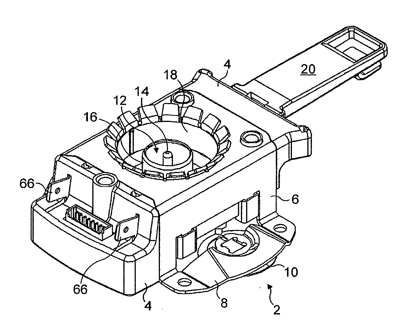
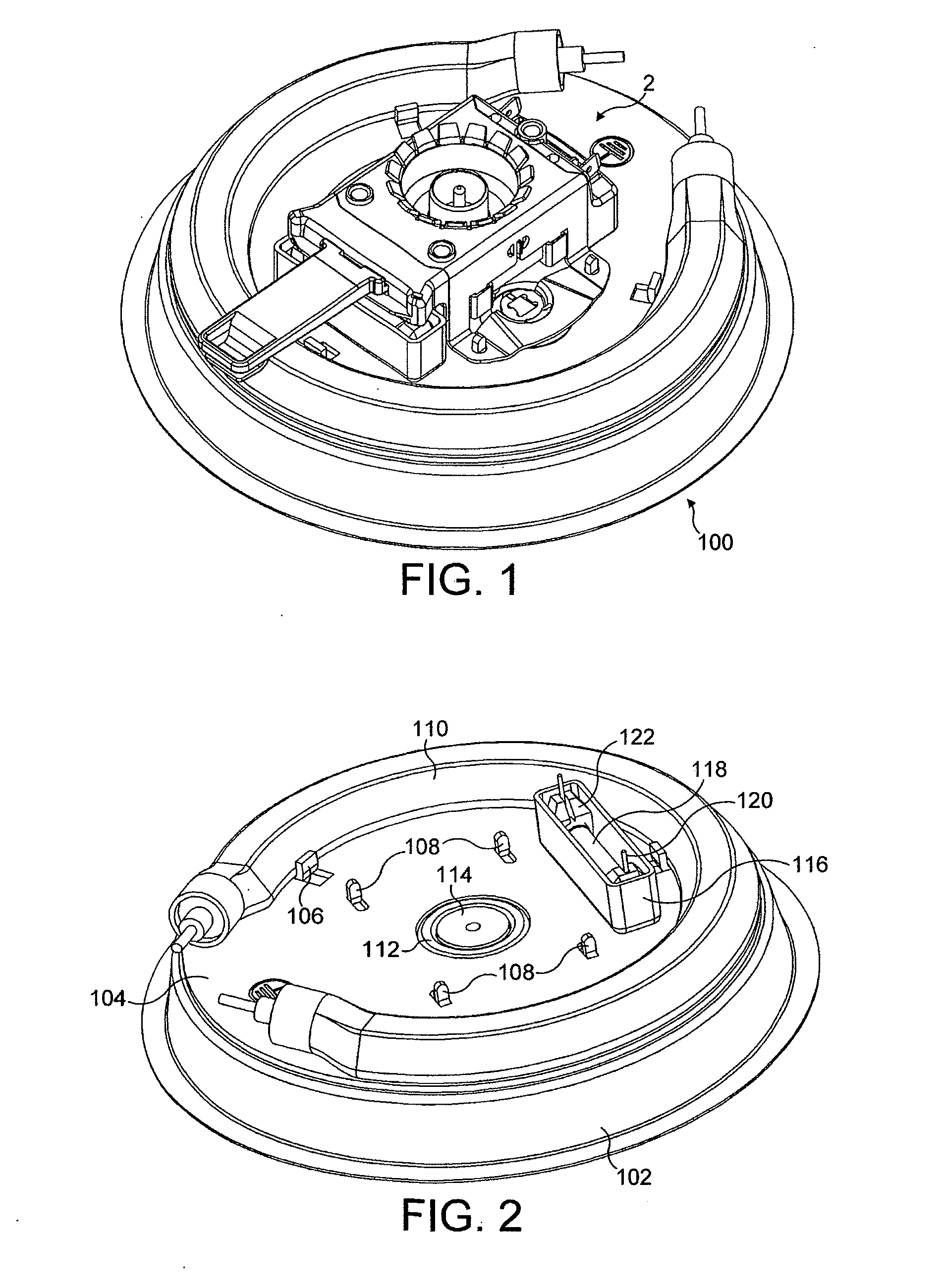
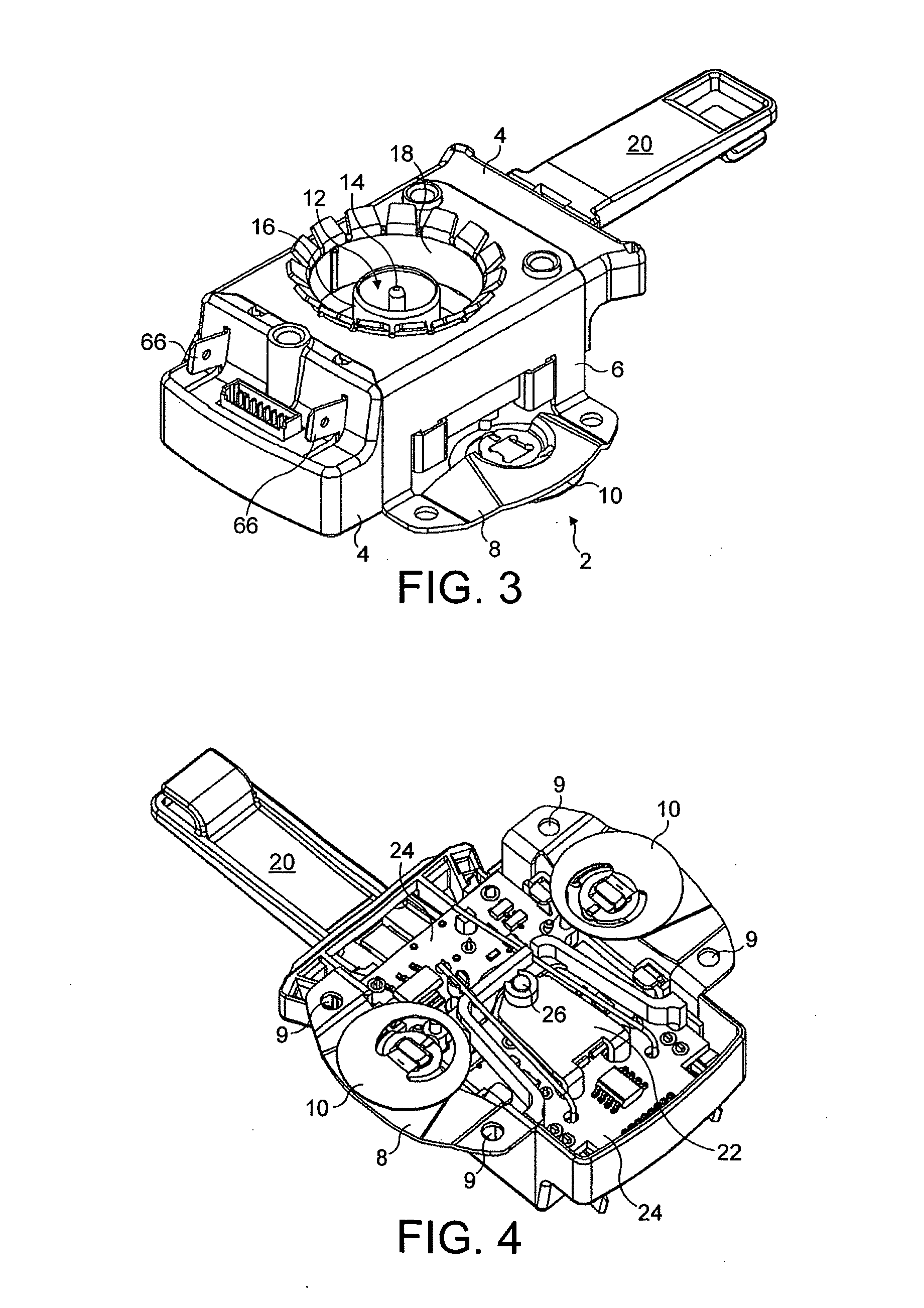
[0054]FIG. 1 shows a control unit 2 which is mounted to an underfloor heater 100 shown more clearly in FIG. 2. The underfloor heater (shown inverted from its in-use orientation for the purposes of explanation) comprises a dish-shaped stainless steel plate 102 which is designed to be mounted so as to close an opening in the base of a liquid heating vessel. Any convenient mounting method may be used. For example although not shown the plate 102 could be provided with an upwardly open peripheral channel to enable it to be fixed using the Applicant's Sureseal fixing system described in greater detail in WO 96 / 18331.

[0055]Brazed to the underside of the plate 102 is an aluminum heat diffuser plate 104. A number of tabs 106, 108 are released from this: respectively to locate a conventional sheathed heating element brazed to the diffuser plate 104; and to attach the control unit 2.

[0056]In the center of the stainless steel plate 102 is an annular wall 112 created by a corresponding annular ...


PUM


Abstract

A liquid heating vessel comprising heating means for heating liquid in the vessel, electronic control means, electromagnetic switching means for interrupting or reducing power to the heating means, and temperature sensing means for providing a signal dependent on the temperature of liquid in the vessel to the control means. The control means is arranged to operate the electromagnetic switching means to interrupt or reduce power to the heating means in response to the control means determining that a pre-determined temperature condition has been reached.

Description

BACKGROUND OF THE INVENTION[0001]1. Field of the Invention[0002]This invention relates to liquid heating vessels, in particular but not exclusively to vessels which are controlled to heat water in various modes of operation.[0003]2. Background Information[0004]It is known to provide liquid heating vessels, for example water boiling vessels, with an electronic control which allows a user to select one of a number of possible modes of operation; for instance heating to a temperature of 80-85° C. which is suitable for coffee; heating to boiling; or keeping a beverage warm. Such electronically controlled vessels can provide an extensive range of possible functions beyond those possible in vessels having a conventional thermo-mechanical control. However, electronic controls are typically significantly more expensive than conventional mechanical controls involving complicated logic circuitry and requiring a number of expensive solid-state components. Consequently such appliances have fail...

Claims


Application Information

Patent Timeline
Patent Type & Authority Applications(United States)
IPC IPC(8): A47J27/21H05B1/00H05B1/02
CPCA47J27/21083H05B1/0269A47J27/21116
Inventor SCOTT, MICHAEL JAMESFENNA, IAINMEEKS, ALAN MICHAEL GEORGE
Owner STRIX LTD
Why Eureka
Try Eureka