Bearing fixing device and bearing unit

a bearing unit and fixing device technology, applied in the direction of bearing unit rigid support, machine support, other domestic objects, etc., can solve the problems of large transmission volume, damaged housing, unsatisfactory assembly efficiency, etc., and achieve the effect of improving assembly efficiency and downsizing the bearing uni

Active Publication Date: 2009-01-01
NSK LTD
View PDF15 Cites 17 Cited by
  • Summary
  • Abstract
  • Description
  • Claims
  • Application Information

AI Technical Summary

Benefits of technology

[0013]The present invention is developed to solve such inconveniences, and it is therefore an object of the invention to provide a rolling bearing fixing device in which an axial length of a housing can be shortened, the transmissions etc., can be downsized, and assembli

Problems solved by technology

However, in the rolling bearing fixing device according to U.S. Pat. No. 5,788,210 described above, since it is necessary to lengthen the axial length of the housing in order to assemble a rolling bearing, the transmission may become large in size.
In addition, when the housing is made of aluminum, if attempting to shorten the axial length of the housing, there

Method used


Image

  • Bearing fixing device and bearing unit
  • Bearing fixing device and bearing unit
  • Bearing fixing device and bearing unit

Examples


first embodiment

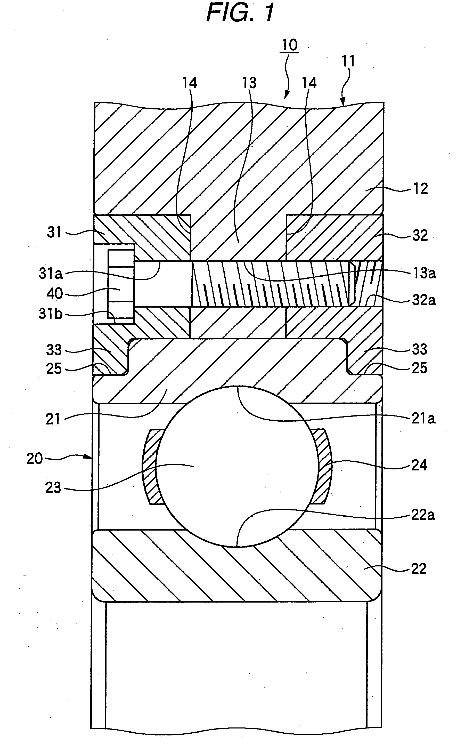
[0069]Hereinafter, a detailed description is given of a rolling bearing fixing device according to the first embodiment of the present invention with reference to FIG. 1 through FIG. 5.

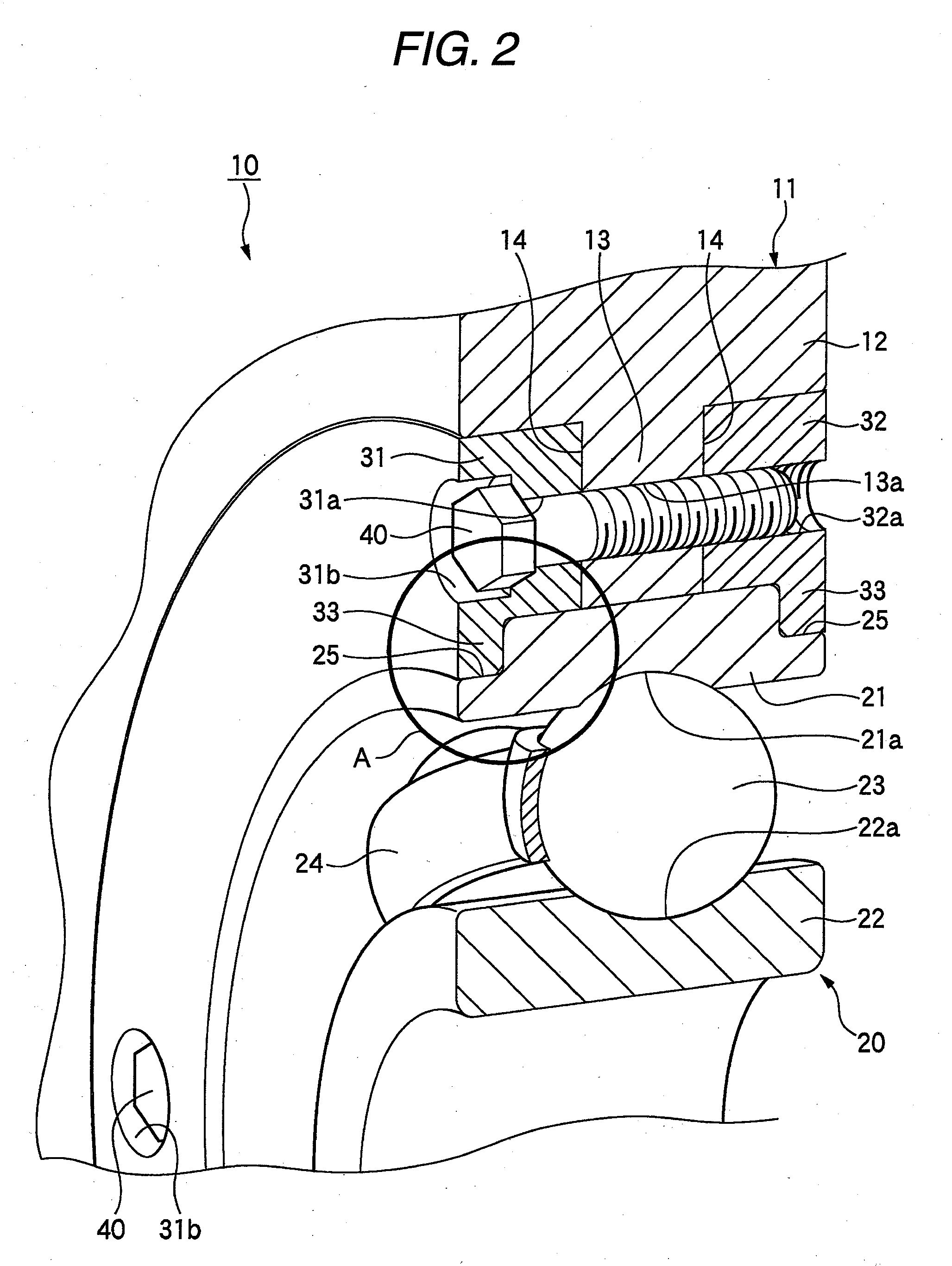
[0070]FIG. 1 is a sectional view showing the major parts of a rolling bearing fixing device according to the first embodiment of the present invention, FIG. 2 is a perspective view showing the rolling bearing fixing device depicted in FIG. 1 from the left side thereof, FIG. 3 is an enlarged view showing the part “A” of FIG. 2, FIG. 4 is a perspective view showing the rolling bearing fixing device depicted in FIG. 1 from the right side thereof, and FIG. 5 is an enlarged view showing the part “B” of FIG. 4.

[0071]As shown in FIG. 1 through FIG. 5, a rolling bearing fixing device 10 according to the first embodiment is provided with a housing 11, a rolling bearing 20 in which a plurality of balls (rolling elements) 23 are rollably located in the circumferential direction between the outer ring 21 and the ...

second embodiment

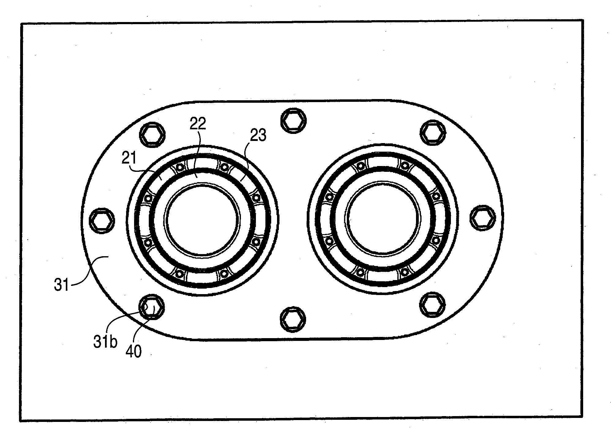
[0082]Next, a detailed description is given of a rolling bearing fixing device according to the second embodiment of the present invention with reference to FIG. 6 and FIG. 7. FIG. 6 is a sectional view showing a rolling bearing fixing device according to the second embodiment of the present invention, and FIG. 7 is a front elevational view showing a rolling bearing fixing device according to the second embodiment.

[0083]The second embodiment is characterized in that a plurality of bearings 20 are altogether assembled in the housing 11 by a pair of fixing plates 31 and 32. The second embodiment is similar to the first embodiment in other points. Therefore, a detailed description thereof is omitted, and only different points will be described below.

[0084]In the second embodiment of the present invention, as shown in FIG. 6 and FIG. 7, two rolling bearings 20 are located adjacent to each other. Two large-diameter holes are provided at positions of the fixing plates 31 and 32, which cor...

third embodiment

[0086]Next, a detailed description is given of a bearing unit according to the third embodiment of the present invention with reference to FIG. 9 through FIG. 13.

[0087]FIG. 9 is a front elevational view showing a bearing unit according to the third embodiment of the present invention, FIG. 10 is a rear side view showing the bearing unit shown in FIG. 9, FIG. 11 is a sectional view showing the bearing unit shown in FIG. 9, FIG. 12 is a front elevational view of a single rolling bearing of the bearing unit shown in FIG. 9, and FIG. 13 is a front elevational view of a single rolling bearing according to a modified version of the bearing unit shown in FIG. 9.

[0088]As shown in FIG. 9 through FIG. 11, a bearing unit 401 according to the third embodiment has two rolling bearings 410 and a housing 430 into which the rolling bearings 410 are fitted and inserted. The rolling bearing 410 includes an outer ring 411, an inner ring 412, and balls 413 that are a plurality of rolling elements rolla...


PUM


Abstract

A rolling bearing fixing device includes at least one bearing having mutually rotatable inner and outer rings, a housing having at least one fitting hole into which the bearing is fitted and a bolt insertion hole, a pair of fixing plates having at least one large-diameter hole and a bolt insertion hole; and a bolt inserted from one axial end into the bolt insertion hole of one fixing plate, the bolt insertion hole of the housing, and the bolt insertion hole of the other fixing plate, and connects the housing with the pair of fixing plates. Both axial end parts of the outer ring are held by the pair of fixing plates in the axial direction, the inner ring is positioned further inwardly of the large-diameter hole of the fixing plates in the radial direction and the inner ring is rotatable with respect to the fixing plates.

Description

BACKGROUND OF THE INVENTION[0001]1. Field of the Invention[0002]The present invention relates to a rolling bearing fixing device for fixing rolling bearings to a housing thereof, and a bearing unit in which a plurality of rolling bearings are fitted and inserted into a housing.[0003]2. Description of Related Art[0004]In recent years, transmissions for vehicles have been made smaller and smaller in line with downsizing of vehicles. For this reason, recently, when fixing a rolling bearing for rotatably supporting a rotation shaft of a transmission, there are known methods such as a stepped portion being provided at the outer ring side of a rolling bearing and the rolling bearing being fixed at a housing by using a retainer plate to shorten the entire length of the transmission.[0005]As a known rolling bearing fixing device using this method, proposed are, a rolling bearing fixing device in which an outer ring is internally fitted to a housing and an axial one end surface of the outer ...

Claims


Application Information

Patent Timeline
IPC IPC(8): H02K5/00F16C19/02
CPCF16C33/586F16C35/077F16C35/045F16C2361/61F16C35/067F16C19/06F16C2226/60F16C19/54
Inventor KATOUGI, TAKAOIKEZAWA, KATSUHIROURAKAMI, SEIGOUHIMEDA, DAISUKESUGIMAN, TOMOHARU
Owner NSK LTD
Why Eureka
Try Eureka