Spindle cooling device

a cooling device and spindle technology, applied in the direction of steering parts, vehicle components, brake systems, etc., can solve the problems of premature failure of the brake assembly, increased wear, and premature failure of the bearing within the hub assembly, so as to prevent overheating and premature failure of parts, and dissipate heat from the brake and hub assembly

Inactive Publication Date: 2009-01-01
GROUND FORCE MARKETING
View PDF4 Cites 12 Cited by
  • Summary
  • Abstract
  • Description
  • Claims
  • Application Information

AI Technical Summary

Benefits of technology

[0006]The present invention provides a spindle or knuckle with cooling fins. The knuckle has raised cooling fins on an outside exterior surface. The fins create cooling channels which direct air upward when the vehicle is in motion. The redirected air passes over and around the brake and hub assemblies. This effectively dissipates heat from the brake and hub assemblies and will help to prevent overheating and premature failure of the parts.

Problems solved by technology

Braking generates heat which increases wear and may cause premature failure of the brake assemblies.
Bearings within the hub assemblies are also prone to premature failure when overheating occurs.
This problem is compounded when vehicles must operate in harsh conditions such as descending steep grades or operating in high temperature environments.
Trucks are often at greatest risk to brake and wheel bearing overheating as they are required to slow or stop heavier loads.

Method used


Image

  • Spindle cooling device
  • Spindle cooling device
  • Spindle cooling device

Examples


Embodiment Construction

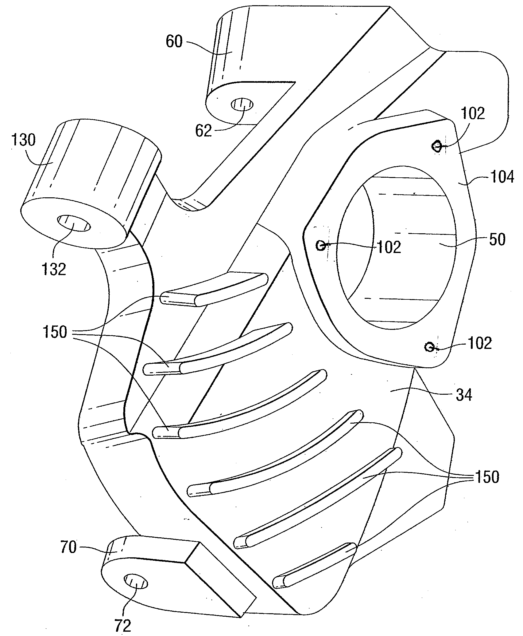
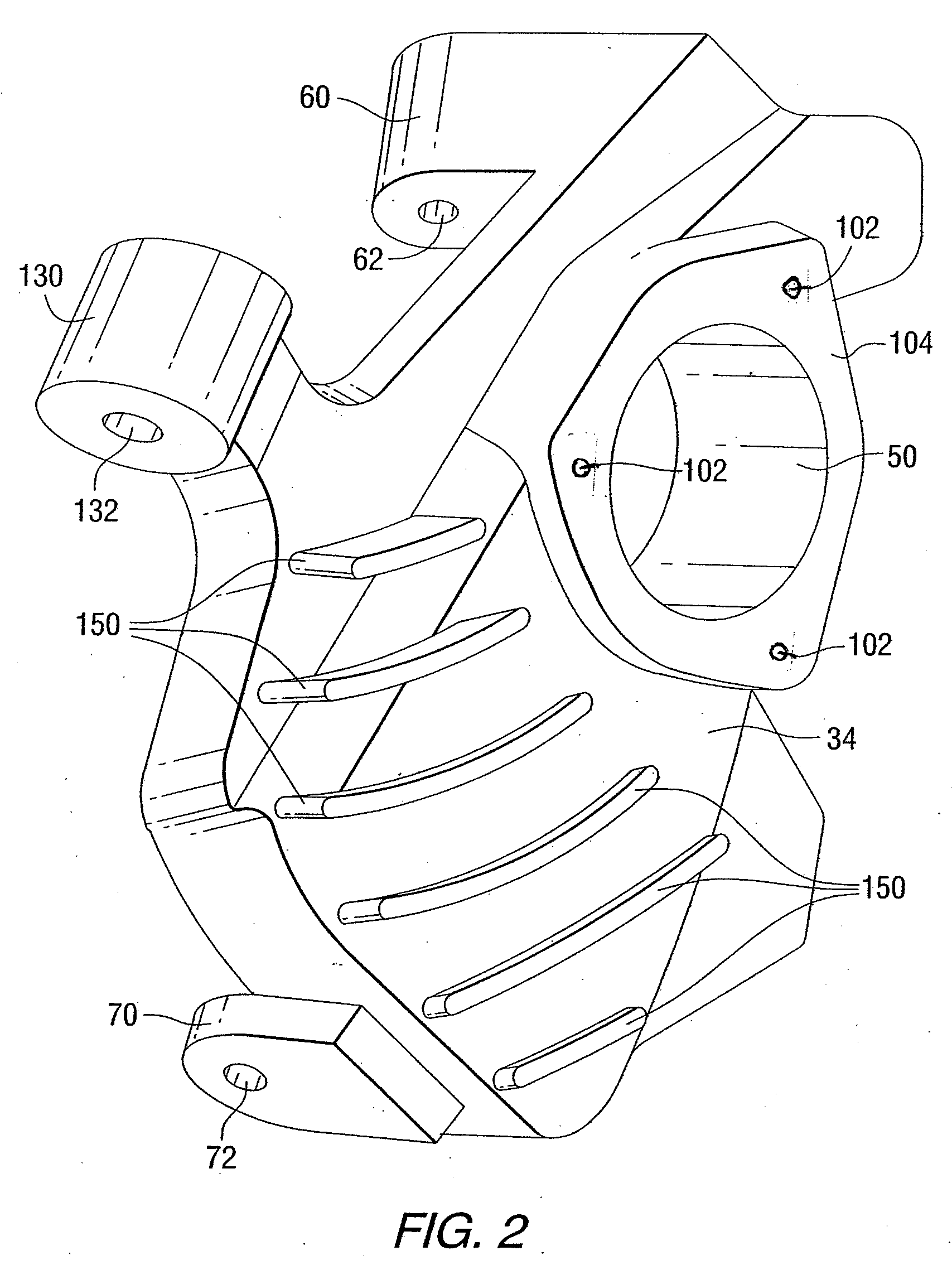
[0015]The present invention provides a steering knuckle with improved cooling for a hub assembly and brake assembly mounted on an exterior surface of the steering knuckle. When a vehicle with spindles of the present invention installed is in motion, the cooling fins of each spindle catch air and direct the flow of the air upward through the channels created by the cooling fins. This forced air travels around the wheel hub assembly, brake rotor, brake caliper and brake pad, effectively cooling this equipment by dissipating heat away from the spindle assembly. As a result, the aforementioned components last longer than components installed on a conventional spindle.

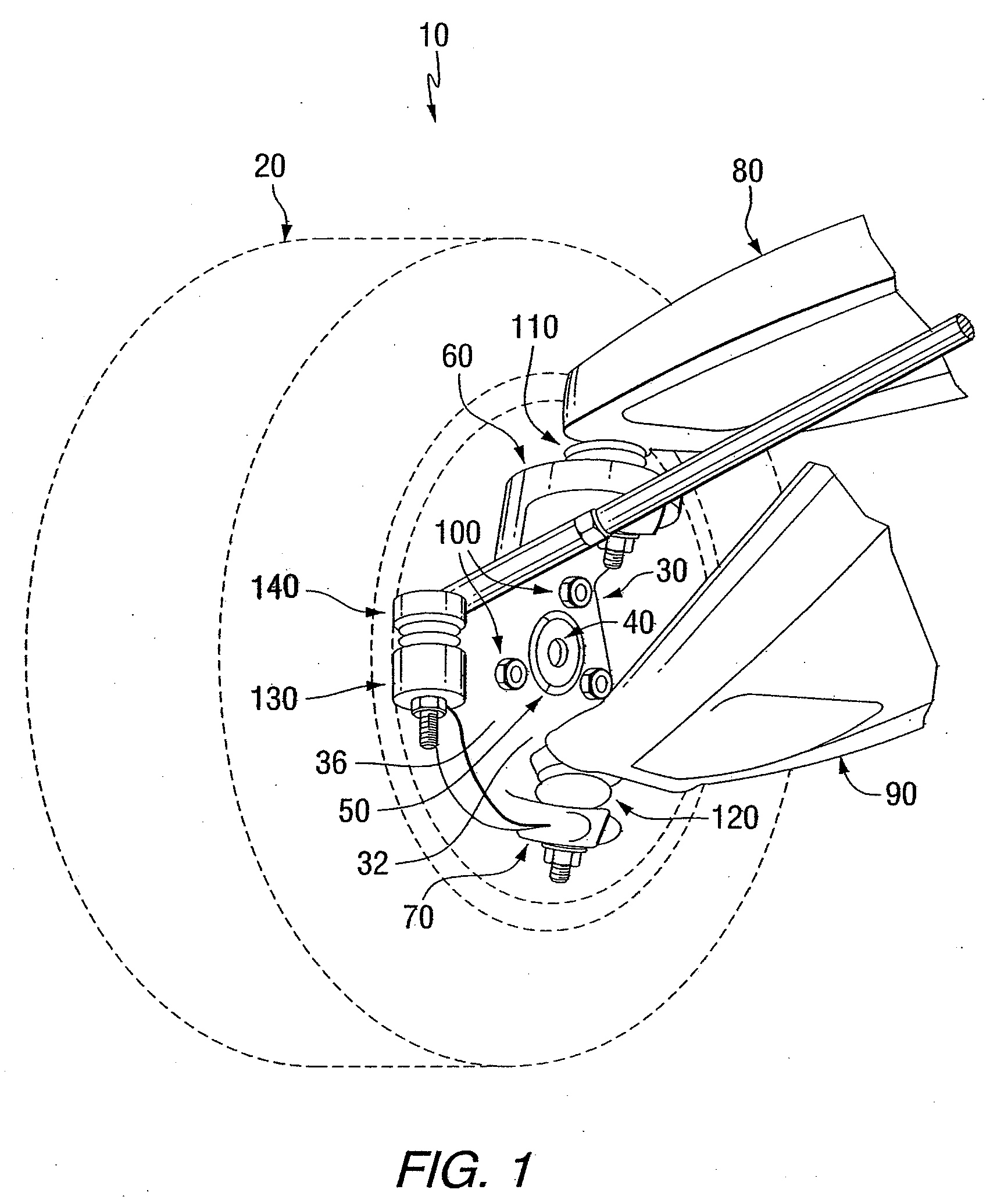
[0016]Referring now to FIG. 1, a suspension assembly 10 of a vehicle is shown. As used herein, the term “vehicle” refers to a wheeled conveyance that transports people or objects including cars, trucks, vans and buses. FIG. 1 illustrates perspective view of the a suspension assembly 10 for a front end of a rear wheel drive ...


PUM


Abstract

A spindle with cooling fins is disclosed. The spindle has raised cooling fins on an outside exterior surface. The fins create cooling channels which direct air upward when the vehicle is in motion. The redirected air passes over and around the brake and hub assemblies. This effectively dissipates heat from the brake and hub assemblies and will help to prevent overheating and premature failure of the parts.

Description

CROSS-REFERENCE TO RELATED APPLICATION[0001]This application claims the benefit of U.S. Provisional Application No. 60 / 946,029 filed Jun. 25, 2007, which is incorporated herein by reference.FIELD OF THE INVENTION[0002]The present invention relates to a steering knuckle for use on the front end of a vehicle.BACKGROUND INFORMATION[0003]A typical spindle or steering knuckle is a component of the front suspension of a vehicle, which attaches the wheel and brake assemblies to the vehicle, and allows the wheels to travel vertically, turn, and rotate. Mounted on the steering knuckle are brake assemblies and hub assemblies on which the wheels of the vehicle are mounted.[0004]Braking generates heat which increases wear and may cause premature failure of the brake assemblies. Bearings within the hub assemblies are also prone to premature failure when overheating occurs. This problem is compounded when vehicles must operate in harsh conditions such as descending steep grades or operating in hi...

Claims


Application Information

Patent Timeline
Patent Type & Authority Applications(United States)
IPC IPC(8): B62D7/18
CPCB60T5/00
Inventor SUMEY, DANIEL J.GERMAN, MARK K.
Owner GROUND FORCE MARKETING
Why Eureka
Try Eureka