Systems and methods for detecting a faulty ground strap connection

a ground strap and connection technology, applied in the direction of testing circuits, hybrid vehicles, instruments, etc., can solve the problems of fatigue or failure of the conductor's insulation of the machine component, the current of the high-voltage power supply may leak to the machine frame,

Active Publication Date: 2009-01-01
CATERPILLAR INC
View PDF16 Cites 48 Cited by
  • Summary
  • Abstract
  • Description
  • Claims
  • Application Information

AI Technical Summary

Benefits of technology

[0007]Systems and methods are disclosed for detecting a faulty ground strap connection for a machine hosting a high voltage system. In one embodiment, a fault detection and compensation system includes a ground strap, a DC power supply electrically referenced to a machine frame, a leakage detection switch connected to the machine frame, a current source controlled by the leakage detection switch, and a voltage measuring device that measures an offset voltage. The fault detection and compensation system further includes a leakage detection and compensation controller that compensates for the unbalanced fault condition by controlling the leakage detection switch and the current source, and determines whether the ground strap is properly connected to the machine frame.

Problems solved by technology

However, under faulty conditions (e.g., insulation failure), electric currents from a high voltage power supply may leak to a machine frame.
Such leakage currents, when significant, may be an indication of machine component fatigue or failure of a conductor's insulation.
While prior art systems, such as the '384 patent, may detect electrical leakage, they do not detect electrical leakage in a balanced fault condition.

Method used


Image

  • Systems and methods for detecting a faulty ground strap connection
  • Systems and methods for detecting a faulty ground strap connection
  • Systems and methods for detecting a faulty ground strap connection

Examples


Embodiment Construction

[0012]Reference will now be made in detail to the disclosed embodiments, examples of which are illustrated in the accompanying drawings. Wherever possible, the same reference numbers will be used in the drawings to refer to the same or like parts.

[0013]In the disclosed embodiments, a machine may refer to a petroleum-electric hybrid powered machine, such as a hybrid-electric vehicle which uses an internal combustion engine and electric batteries, fuel cells, or other electrical power sources to power electric motors. A machine may also refer to any type of machine, such as an electric vehicle, with one or more electric motors and an electric power source. A frame may refer to the conductive support structure or housing of the machine including an electrical power source.

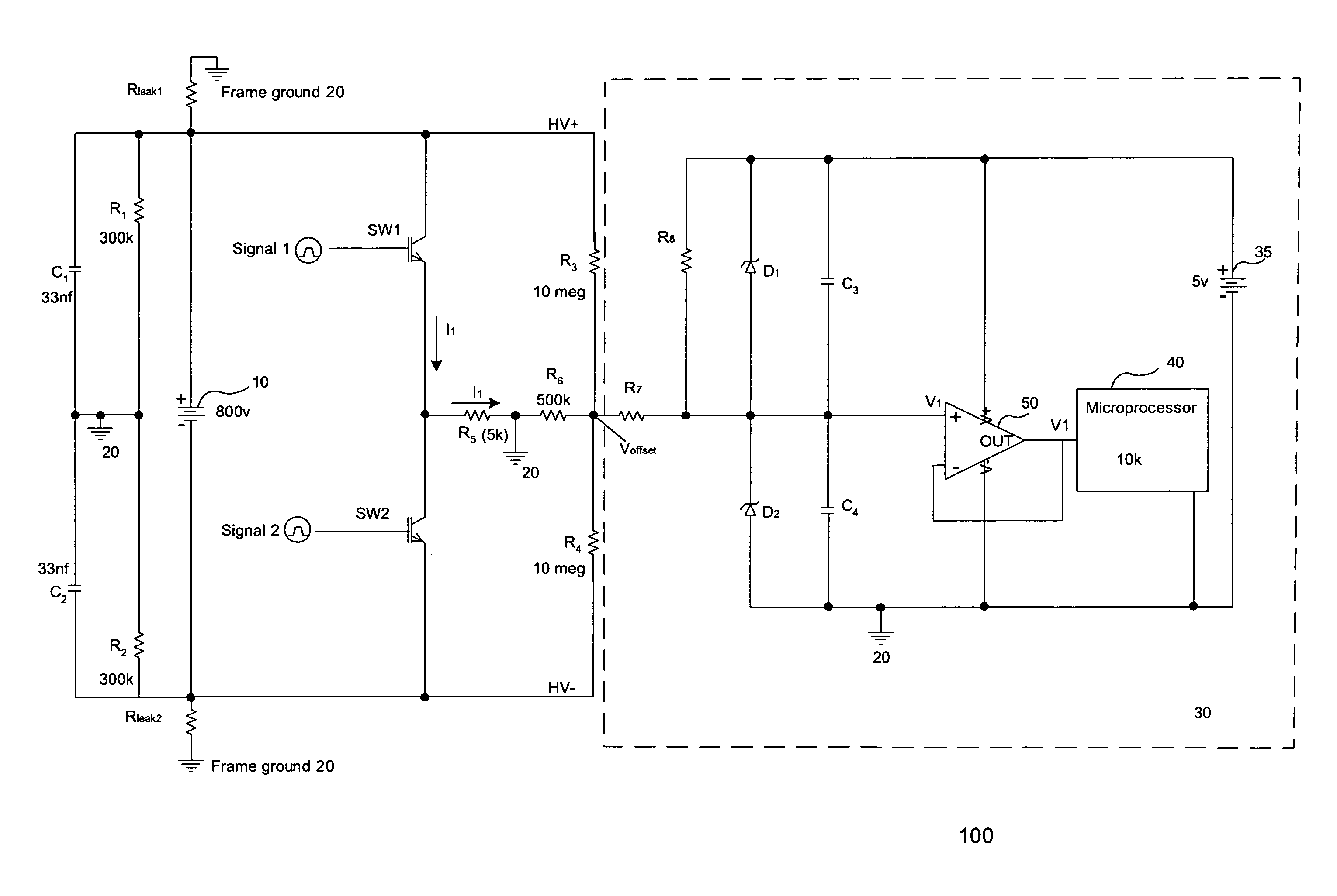
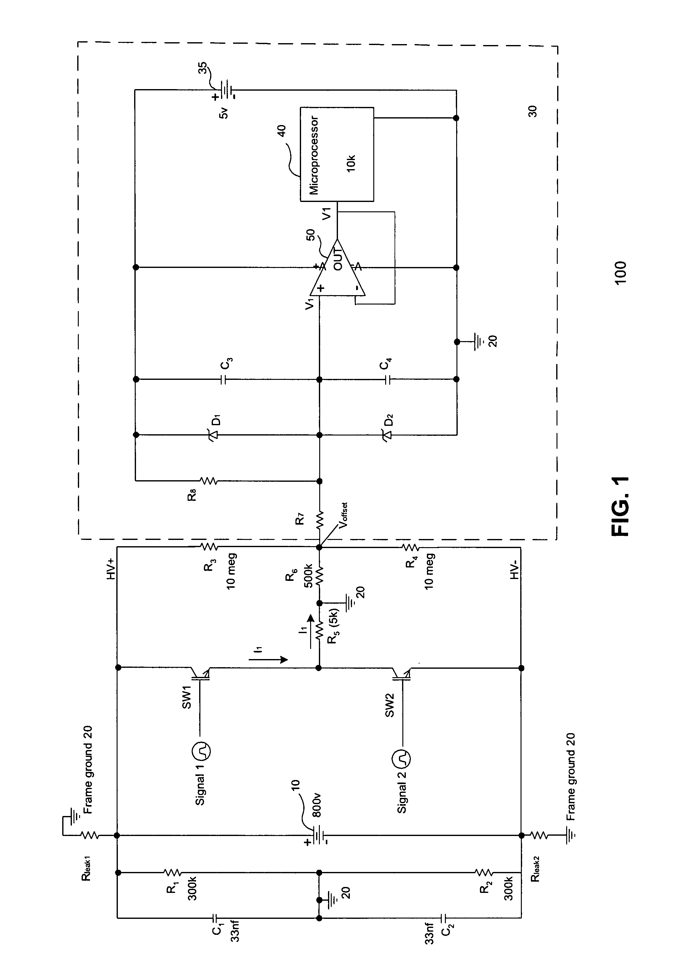
[0014]FIG. 1 illustrates an exemplary electrical leakage detection and compensation circuit 100 consistent with the disclosed embodiments. Electrical leakage detection and compensation circuit 100 may be used to compe...


PUM


Abstract

Systems and methods are disclosed for detecting a faulty ground strap connection for a machine hosting a high voltage system. In one embodiment, a fault detection and compensation system includes a ground strap, a DC power supply electrically referenced to a machine frame, a leakage detection switch connected to the machine frame, a current source controlled by the leakage detection switch, and a voltage measuring device that measures an offset voltage. The fault detection and compensation system further includes a leakage detection and compensation controller that compensates for the unbalanced fault condition by controlling the leakage detection switch and the current source, and determines whether the ground strap is properly connected to the machine frame.

Description

TECHNICAL FIELD[0001]This disclosure relates generally to electrical leakage detection and compensation systems, and more particularly, to an electrical leakage detection and compensation system for compensating for unbalanced leakage currents and detecting balanced leakage currents in high voltage direct current (HVDC) systems used in machines.BACKGROUND[0002]An HVDC power supply system is required for driving an electric machine that incorporates a high voltage electrical drive motor and electric auxiliaries. The integrity of the high voltage system is critical to the reliability and integrity of the machine. Typically, the machine frame is electrically insulated from the terminals or conductors of the high voltage power supply.[0003]Under normal working conditions, DC leakage currents on the order of microamps exist between the conductors of the high voltage power supply and the machine frame. Thus, the leakage resistances between the conductors of the high voltage power supply a...

Claims


Application Information

Patent Timeline
Patent Type & Authority Applications(United States)
IPC IPC(8): G01R31/14G01R31/00G08B21/00H02H3/08
CPCB60L3/0023B60L3/0069H02H3/14B60W20/00G01R31/025B60W10/08G01R31/52
Inventor LINDSEY, ROBERT WAYNESELVEY, DUSTIN CRAIGWILD, ARTHURSYCHRA, ROBERT ROY
Owner CATERPILLAR INC
Why Eureka
Try Eureka