Electroacoustic transducer

a transducer and electroacoustic technology, applied in the direction of transducer details, electrical transducers, electrical apparatus, etc., can solve the problems of difficult to increase the sound pressure, achieve the effect of facilitating the installation of voice coils, reliably retaining voice coils, and facilitating voice coil installation

Inactive Publication Date: 2009-01-01
CITIZEN ELECTRONICS CO LTD
View PDF0 Cites 14 Cited by
  • Summary
  • Abstract
  • Description
  • Claims
  • Application Information

AI Technical Summary

Benefits of technology

[0014]The electroacoustic transducer may be arranged as follows. The joint portion of the diaphragm has a tubular coil support extending coaxially with the voice coil, and the voice coil is mounted on the inner or outer peripheral surface of the coil support. With this arrangement, the installation of the voice coil is facilitated.
[0015]Specifically, the electroacoustic transducer may be arranged as follows. The coil support has an L-shaped sectional configuration having an annular support portion extending radially outward from the lower end edge of the coil support, and the voice coil is in contact with both the outer peripheral surfac...

Problems solved by technology

With the structure of the electroacoustic transducer disclosed in Japanese Patent Application Publication No. 2003-143676, it is difficult to ...

Method used


Image

  • Electroacoustic transducer
  • Electroacoustic transducer
  • Electroacoustic transducer

Examples


first embodiment

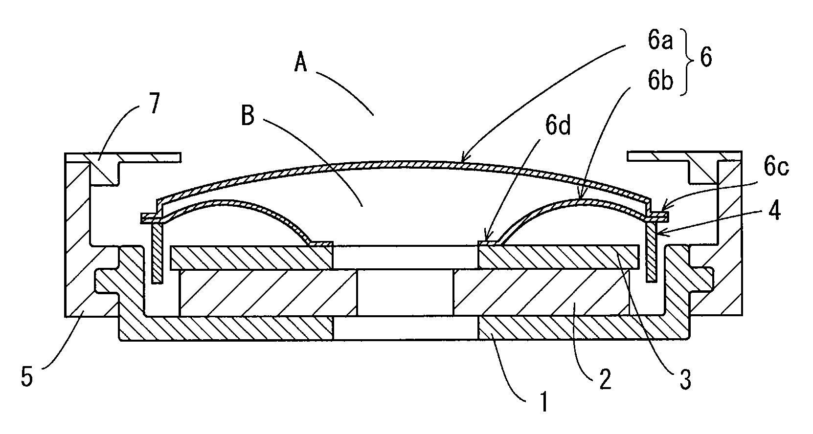
[0034]FIG. 1 is a sectional view of an electroacoustic transducer according to a first embodiment of the present invention. In FIG. 1, the electroacoustic transducer has a magnetic circuit unit including a cup-shaped yoke 1 and a combination of a disk-shaped magnet 2 and a flat plate-shaped top plate 3 that are successively stacked on the inner bottom surface of the yoke 1, in the same way as in the above-described prior art. The electroacoustic transducer further has a voice coil 4 inserted into a magnetic gap formed between the inner peripheral surface of the yoke 1 and the outer peripheral surface of the top plate 3. The yoke 1 is insert-molded in a resinous frame 5. A diaphragm 6 is made of a resin sheet, e.g. PEN (polyethylene naphthalate) or PET (polyethylene terephthalate), and has a dome-shaped central portion 6a and an annular portion 6b disposed underneath the central portion 6a. The outer peripheral edge of the central portion 6a and the outer peripheral edge of the annul...

second embodiment

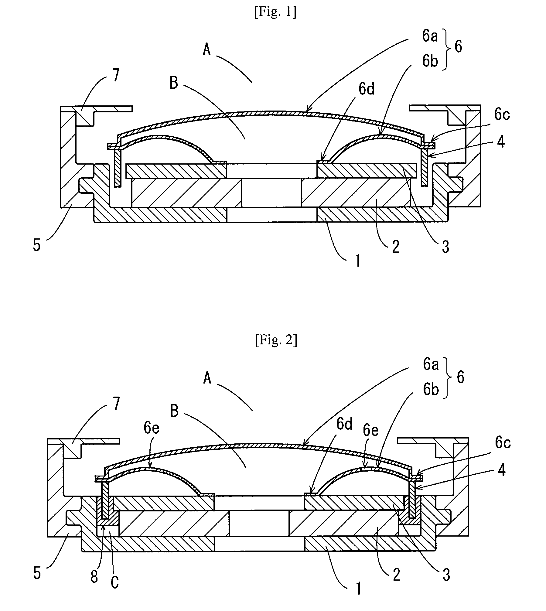
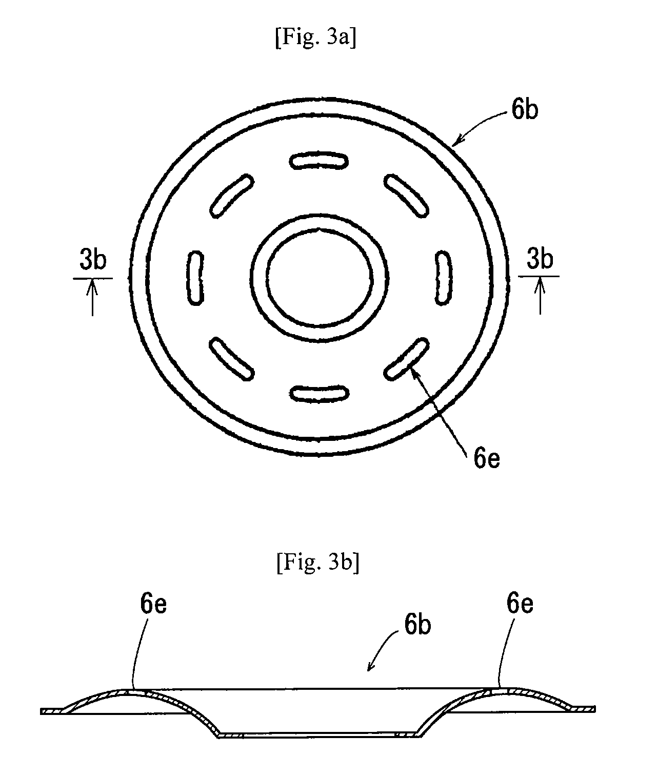
[0038]FIG. 2 shows an electroacoustic transducer according to a second embodiment of the present invention. FIGS. 3a and 3b are a plan view and a sectional view, respectively, showing the annular portion 6b of the diaphragm 6 of the electroacoustic transducer according to the second embodiment. The second embodiment differs from the first embodiment in that the annular portion 6b of the diaphragm 6 is provided with air holes 6e so as to be permeable to air. As a modification of this embodiment, the annular portion 6b may be made of an air-permeable material such as a mesh material. In this embodiment, the magnetic gap is filled with a liquid 8 (e.g. a magnetic fluid, or silicone oil), thereby blocking communication between the spaces A and B.

third embodiment

[0039]FIGS. 4 and 5 show an electroacoustic transducer according to a third embodiment of the present invention. This embodiment is substantially the same as the second embodiment. The third embodiment differs from the second embodiment in that air holes (through-holes) 1a are provided in the bottom of the yoke 1 at positions in an annular area corresponding to the magnetic gap. When the voice coil 4 is driven to vibrate with a large amplitude, the pressure in the space C varies to suppress the movement of the voice coil 4 undesirably. Therefore, it is preferable to provide air holes 1a in the bottom of the yoke 1 in the case of a speaker in which the voice coil 4 may vibrate with a large amplitude, although such air holes 1a are not necessary when there is no possibility of the voice coil 4 vibrating with a large amplitude.


PUM


Abstract

An electroacoustic transducer includes a magnetic circuit unit that forms a magnetic gap, a voice coil inserted into the magnetic gap, and a diaphragm to which the voice coil is connected. The diaphragm has a central portion having an outer peripheral edge and an annular portion disposed underneath the central portion. The annular portion has an outer peripheral edge corresponding to the outer peripheral edge of the central portion, and an inner peripheral edge secured to the magnetic circuit unit. The diaphragm further has a joint portion formed at the outer peripheral edges of the central and annular portions, and the outer peripheral edges are joined together. The voice coil is disposed underneath the central portion of the diaphragm and joined to the joint portion.

Description

REFERENCE TO THE RELATED APPLICATIONS[0001]This application claims priority under 35 U.S.C. § 119 to Japanese Patent Application No. JP2007-171499 filed on Jun. 29, 2007, the entire content of which is hereby incorporated by reference.BACKGROUND OF THE INVENTION[0002]1. Technical Field of the Invention[0003]The present invention relates to an electroacoustic transducer that may be incorporated into electronic devices such as mobile phones and personal digital assistants (PDAs) to inform the user of an incoming call by vibrating a diaphragm.[0004]2. Description of the Related Arts[0005]Conventionally, mobile communications devices such as mobile phones and PDAs are arranged to inform the user of an incoming call by selectively generating beep sound or melody sound, or vibrating the housing of the device instead of producing sound. Such an electroacoustic transducer is disclosed, for example, in Japanese Patent Application Publication No. 2003-143676. The electroacoustic transducer ha...

Claims


Application Information

Patent Timeline
IPC IPC(8): H04R9/06
CPCH04R9/02
Inventor FURUYA, MASAHITO
Owner CITIZEN ELECTRONICS CO LTD
Why Eureka
Try Eureka