Optical switching device

a switching device and optical technology, applied in the field of optical switching devices, can solve the problems of difficult to smoothly upgrade the conventional nn switch, difficult to miniaturize the device or reduce the cost of the device, etc., and achieve the effect of easy scaling and low coa

Active Publication Date: 2009-01-01
FUJITSU LTD
View PDF6 Cites 39 Cited by
  • Summary
  • Abstract
  • Description
  • Claims
  • Application Information

AI Technical Summary

Benefits of technology

[0011]The present invention was made under the background circumstances described above. An object of the present invention is to provide an optical switching device in which only a small number of switching elements is used for realizing miniaturization and a low coat and the scale of which can easily be increased in the case of increasing the number of connection ports.

Problems solved by technology

Therefore, it is difficult to miniaturize a device or reduce the costs of a device.
Furthermore, if a small-scale switch is installed at the beginning and is switched later to a large-scale switch at the time of an increase in the number of connections, it is difficult to smoothly upgrade the conventional N×N switch.

Method used


Image

  • Optical switching device
  • Optical switching device
  • Optical switching device

Examples


Embodiment Construction

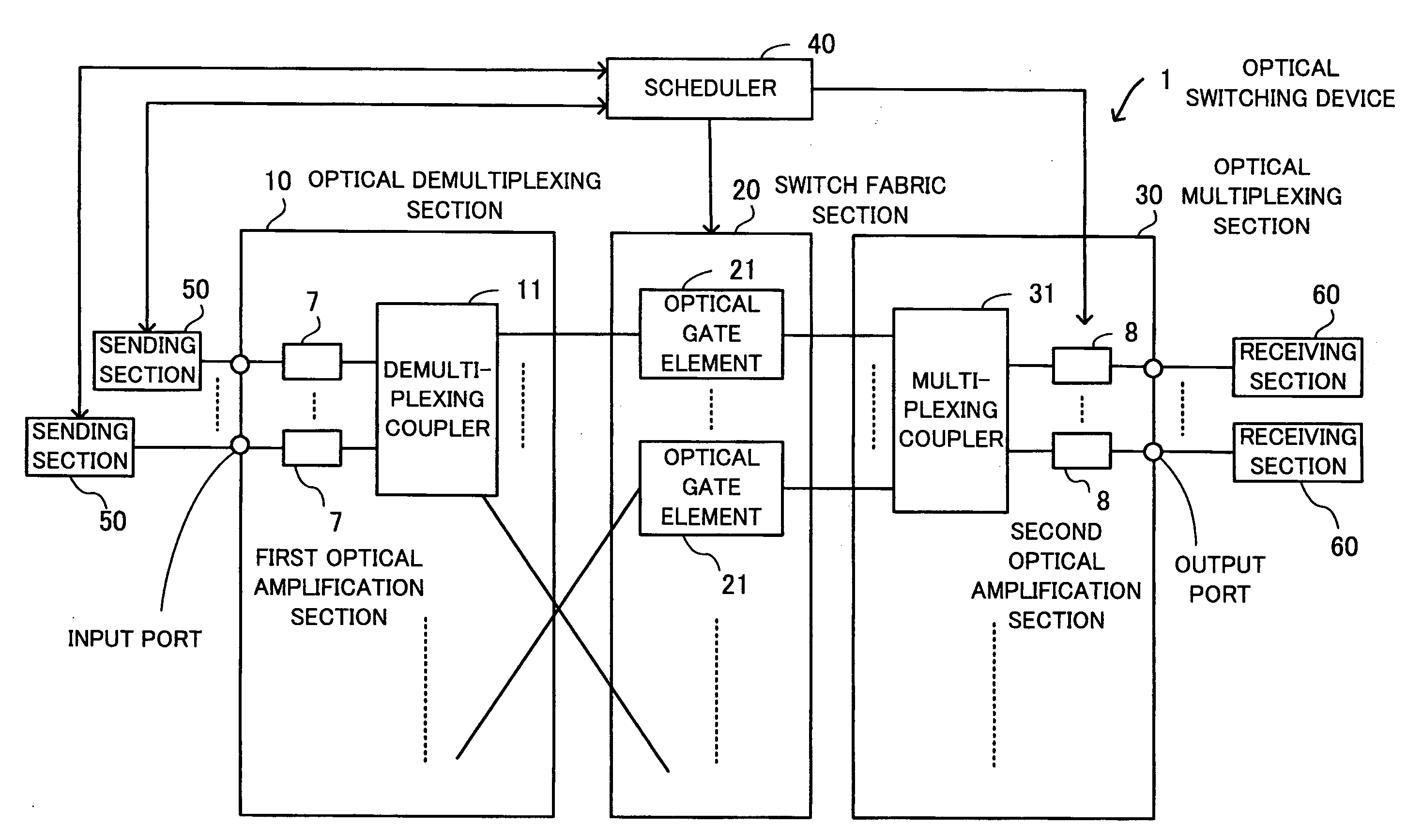
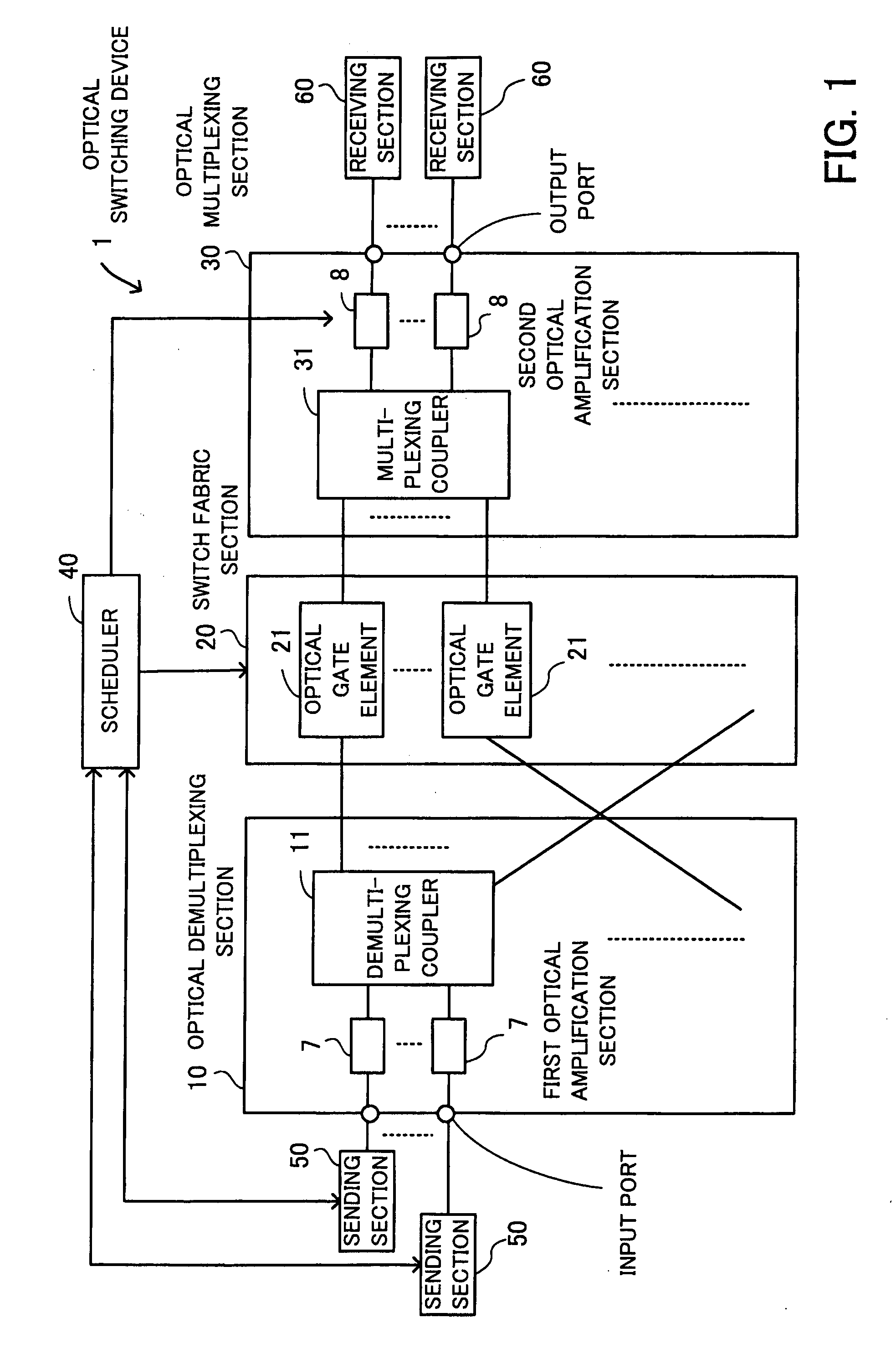
[0032]Embodiments of the present invention will now be described with reference to the drawings. FIG. 1 is a view for describing the principles underlying an optical switching device according to the present invention. An optical switching device 1 comprises an optical demultiplexing section 10, a switch fabric section 20, an optical multiplexing section 30, a scheduler 40, sending sections 50, receiving sections 60, first optical amplification sections 7, and second optical amplification sections 8 and switches an optical packet.

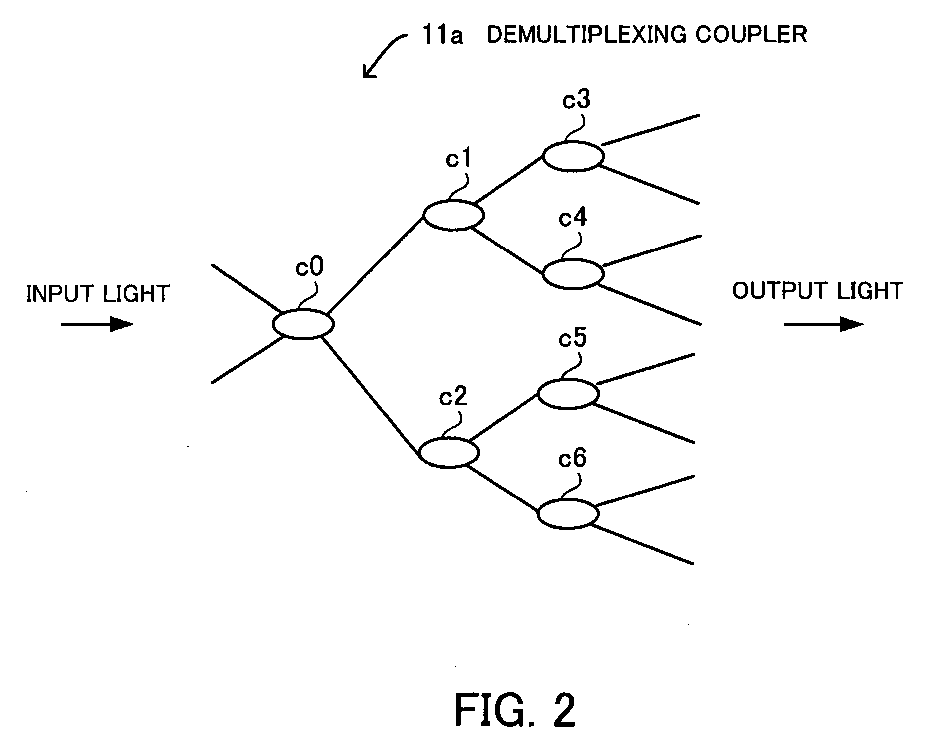
[0033]The optical demultiplexing section 10 has 2n (n=1, 2, 3, . . . ) input ports and 2m (m>n) output ports and includes demultiplexing couplers 11 for demultiplexing input optical packets. m>n, so the number (2m) of the output ports is larger than the number (2n) of the input ports.

[0034]The switch fabric section 20 includes optical gate elements (SOAs) 21 for switching optical packets outputted from the optical demultiplexing section 10 by switch drive c...


PUM


Abstract

An optical switching device the size and costs of which are reduced by decreasing the number of switching elements and which can flexibly accommodate the expansion of the number of ports. An optical demultiplexing section has 2n (n=1, 2, 3, . . . ) input ports and 2m (m>n) output ports and includes demultiplexing couplers for demultiplexing input optical packets. A switch fabric section includes optical gate elements for switching optical packets outputted from the optical demultiplexing section by switch drive control. An optical multiplexing section has 2m input ports and 2n output ports and includes multiplexing couplers for multiplexing the optical packets which pass through the optical gate elements. A scheduler exercises control over an entire optical packet switching process.

Description

CROSS-REFERENCE TO RELATED APPLICATIONS[0001]This application is based upon and claims the benefits of priority from the prior Japanese Patent Application No. 2007-152823, filed on Jun. 8, 2007, the entire contents of which are incorporated herein by reference.BACKGROUND OF THE INVENTION[0002](1) Field of the Invention[0003]This invention relates to an optical switching device and, more particularly, to an optical switching device for switching an optical packet (optical signal).[0004](2) Description of the Related Art[0005]Various systems are devised as next generation optical access networks for transmitting an optical signal to a subscriber system without converting the optical signal into an electrical signal. For example, a broadband passive optical network (B-PON) in which an asynchronous transfer mode (ATM) frame is sent, an Ethernet (registered trademark) passive optical network (E-PON) in which an Ethernet frame is sent, a GE-PON in which Gigabit Ethernet is applied, and th...

Claims


Application Information

Patent Timeline
Patent Type & Authority Applications(United States)
IPC IPC(8): H04J14/00
CPCH04J14/0227H04Q11/0005H04Q2011/0011H04Q2011/0013H04Q2011/0016H04J14/025H04Q2011/0039H04Q2011/005H04Q2011/0052H04J14/0246H04Q2011/0024
Inventor KAI, YUTAKAAOKI, YASUHIKO
Owner FUJITSU LTD
Why Eureka
Try Eureka