Recording apparatus and method for controlling the recording apparatus

Active Publication Date: 2009-01-01
CANON KK
View PDF6 Cites 27 Cited by
  • Summary
  • Abstract
  • Description
  • Claims
  • Application Information

AI Technical Summary

Benefits of technology

[0037]Exemplary embodiments of the present invention are directed to a conveyance control method and a recording control method capable of suppressing adverse effects caused by eccentricity of a conveyance roller and capable of accurately controlling recording even when the inside of a recording apparatus is unclean.

Problems solved by technology

However, if the conveyance belt 3 causes a change in traveling speed due to eccentricity of the conveyance roller 4, the above-described control based on a rotary encoder is subjected to adverse effects.
Similarly, if the conveyance belt 3 has irregularity in thickness, the conveyance belt 3 causes a change in traveling speed and, therefore, the above-described control is subjected to adverse effects.
A similar problem occurs in a recording apparatus configured to convey a recording medium with rollers (e.g., serial type recording apparatus).
In any case, the quality of a recorded image deteriorates.
However, if the conveyance belt is unclean, the second method cannot accurately read the moving speed of the conveyance belt.
For example, a conveyance belt in an inkjet recording apparatus tends to be unclean due to small ink droplets and paper dust.
Similarly, a conveyance belt in an electrophotographic recording apparatus tends to be unclean due to residual toner and paper dust.

Method used


Image

  • Recording apparatus and method for controlling the recording apparatus
  • Recording apparatus and method for controlling the recording apparatus
  • Recording apparatus and method for controlling the recording apparatus

Examples


first exemplary embodiment

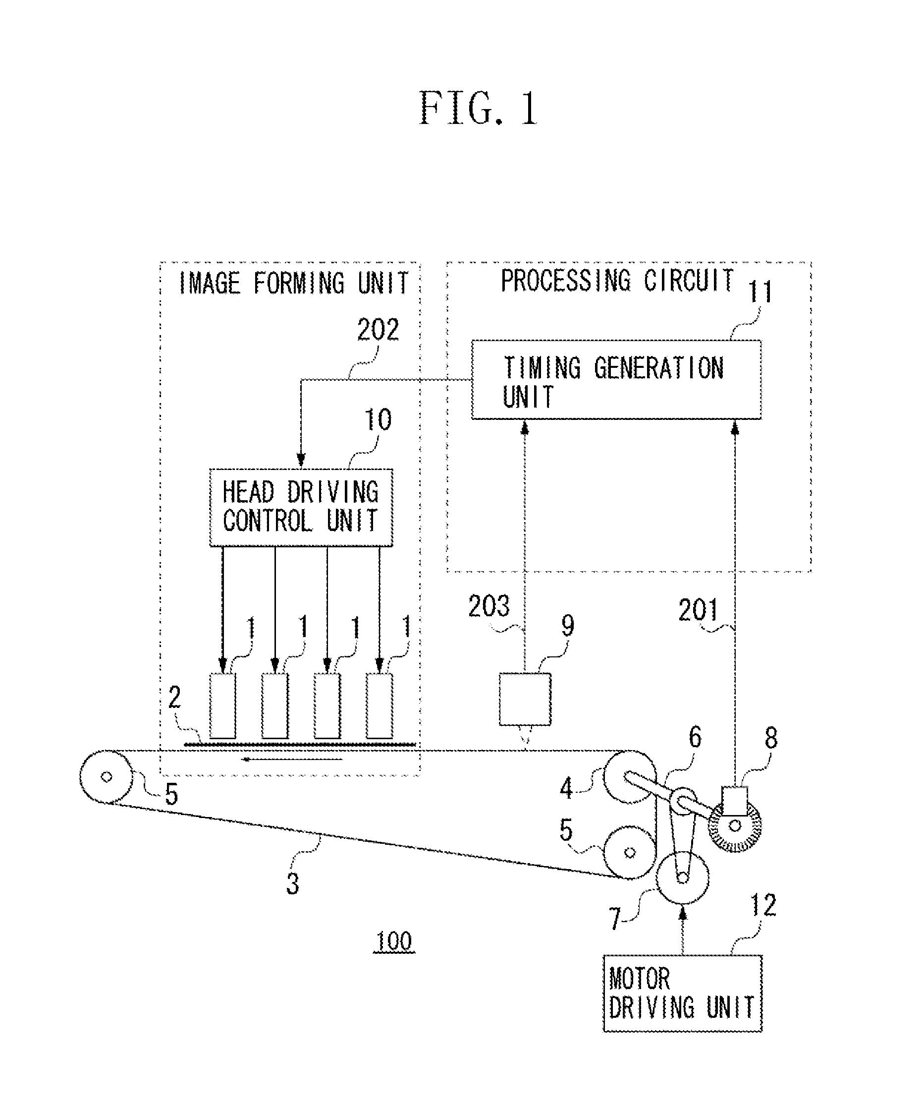
[0077]FIG. 1 illustrates a recording apparatus 100 according to a first exemplary embodiment of the present invention. The recording apparatus 100 includes a plurality of recording heads 1 sequentially positioned in a conveyance direction of a recording medium. The recording head 1 includes a plurality of nozzles arrayed in a direction perpendicular to the conveyance direction of a recording medium.

[0078]An example recording apparatus including a total of four inkjet recording heads 1 performs recording on a recording medium while conveying the recording medium with a conveyance belt. The recording apparatus performs feedback control to realize image formation reflecting variations in conveyance.

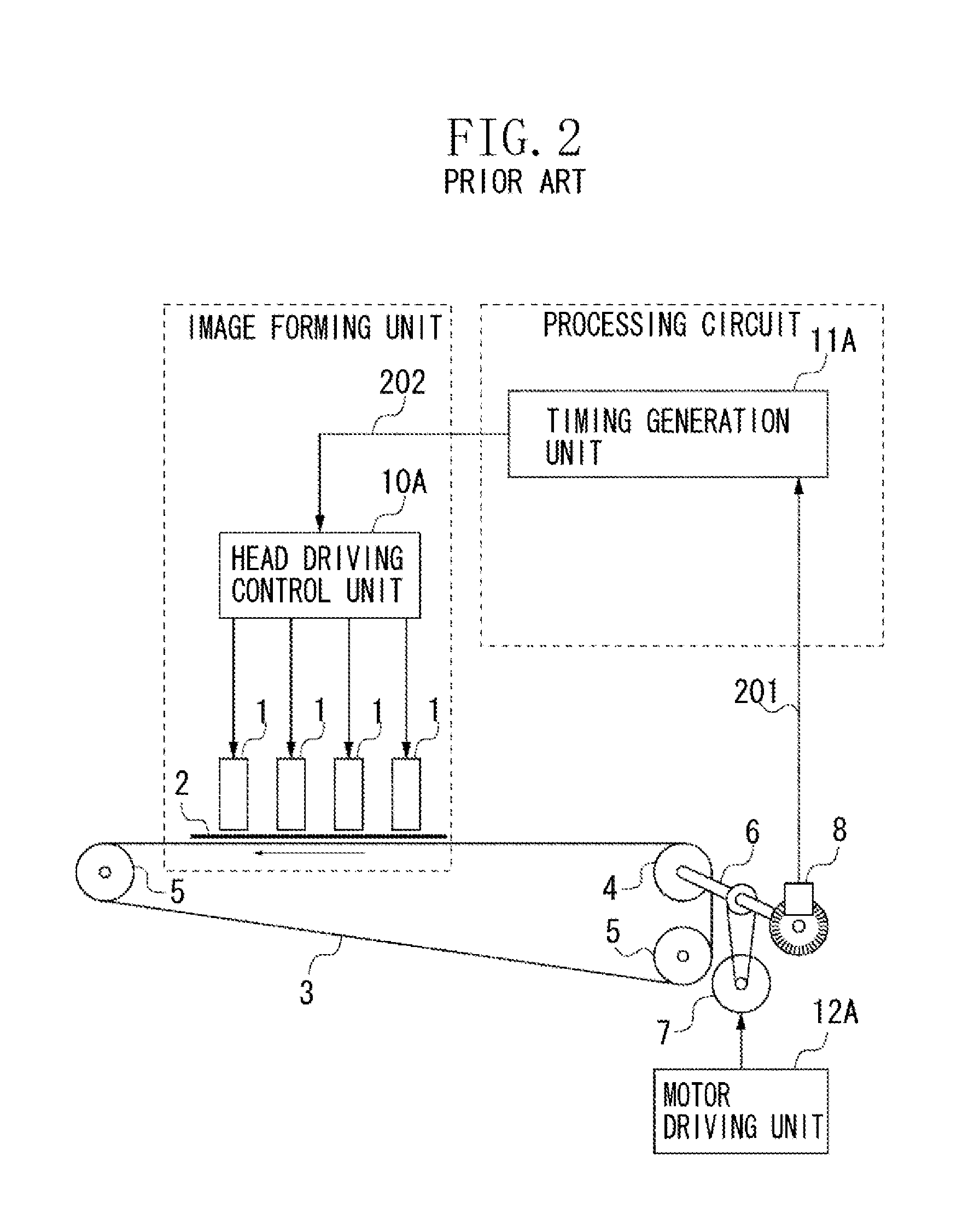
[0079]Reference numerals illustrated in FIG. 1 are similar to those illustrated in FIGS. 2 and 3. In the following description, a rotary encoder 8 is referred to as “rotation detection sensor.”

[0080]To perform recording an image, the recording apparatus 100 rotates a conveyance motor 7 at a ...

second exemplary embodiment

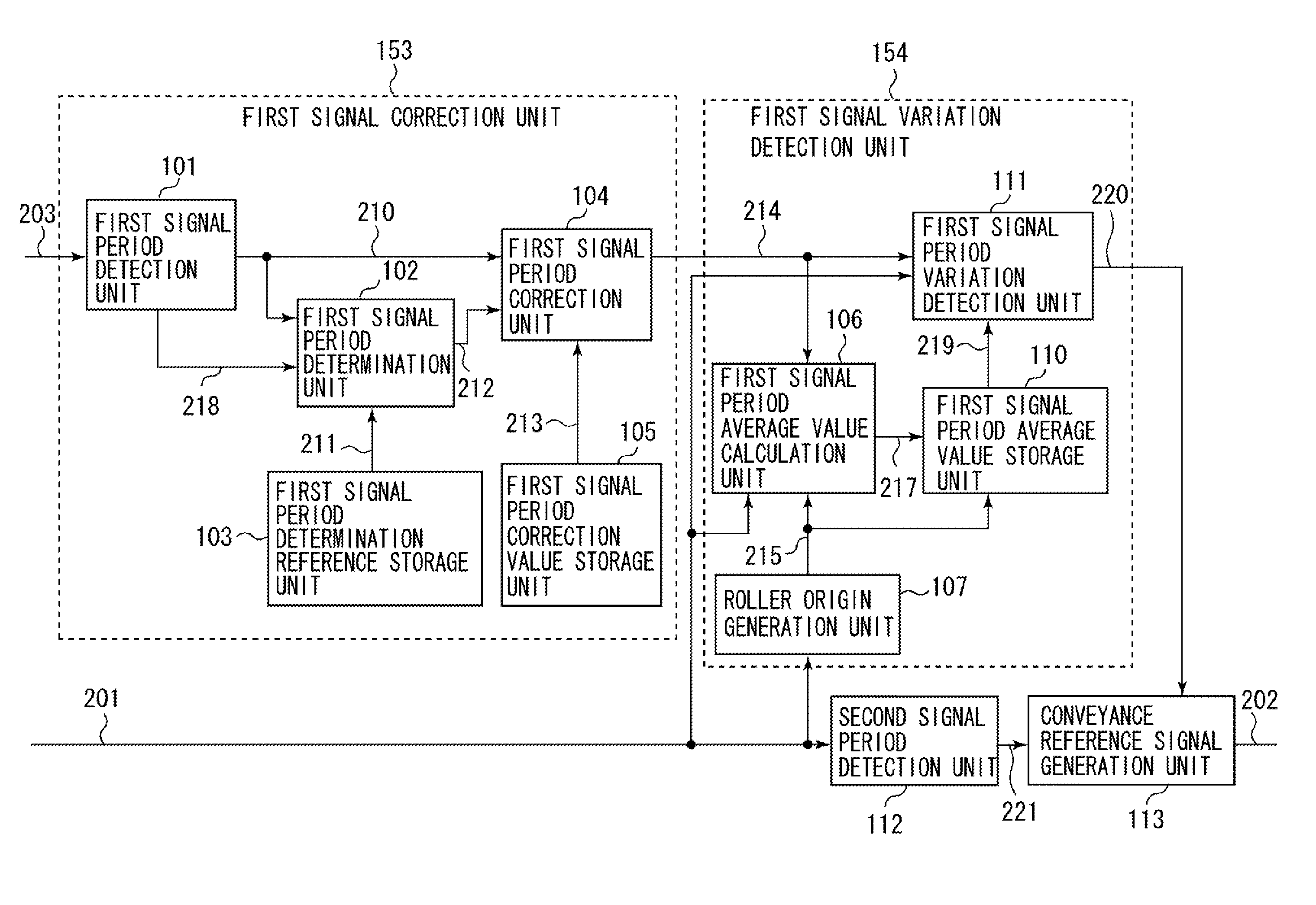
[0130]FIG. 15 illustrates an example correction control unit according to a second exemplary embodiment of the present invention. The first signal correction unit 153 of the timing generation unit 11 according to the second exemplary embodiment is similar to the first signal correction unit 153 illustrated in FIG. 10 except that the first signal period information signal 210 is input to both the first signal period determination reference storage unit 103 and the first signal period correction value storage unit 105.

[0131]After the recording apparatus performs initialization processing (power source turn-on processing) and performs a predetermined conveyance operation, the first signal correction unit 153 stores the processed data into the first signal period determination reference storage unit 103 and the first signal period correction value storage unit 105.

[0132]More specifically, the second exemplary embodiment calculates an average value of the first signal period information ...

third exemplary embodiment

[0135]FIG. 16 illustrates an example correction control unit according to a third exemplary embodiment of the present invention. The first signal correction unit 153 according to the third exemplary embodiment is similar to the first signal correction unit 153 illustrated in FIG. 10 except that the corrected first signal period information signal 214 is input to the first signal period determination reference storage unit 103 and to the first signal period correction value storage unit 105. The block diagram illustrated in FIG. 16 is different from the block diagram illustrated in FIG. 15 in that the first signal period information signal 210 is replaced with the corrected first signal period information signal 214, which is input to the first signal period determination reference storage unit 103 and to the first signal period correction value storage unit 105.

[0136]The first signal correction unit 153 illustrated in FIG. 16 can correct information including abnormality based on al...


PUM


Abstract

A recording apparatus includes a recording unit configured to record an image on a recording medium, a roller configured to convey the recording medium, a first signal generation unit configured to generate a first period signal according to a movement of the recording medium, a second signal generation unit configured to generate a second period signal according to a rotation of the roller, a correction unit configured to correct the first period signal when a period value of the first period signal is outside a predetermined range, an information generation unit configured to generate variation information of a moving speed of the recording medium based on the first period signal, and a control unit configured to control recording on the recording medium based on the variation information and the second period signal.

Description

BACKGROUND OF THE INVENTION[0001]1. Field of the Invention[0002]The present invention relates to a recording apparatus that performs recording on a recording medium and a method for controlling the recording apparatus. Furthermore, the present invention relates to a control operation for conveying a recording medium and a control operation for a recording unit.[0003]2. Description of the Related Art[0004]Recent recording apparatuses are capable of recording high-quality images at higher speeds. To realize high-quality and high-speed image formation, there are various methods for controlling conveyance systems of recording apparatuses.[0005]A first method is described below. As discussed in Japanese Patent Application Laid-Open No. 2002-128313, a conveyance roller includes an optical rotary encoder that generates a signal to be used for a conveyance control operation. The conveyance control operation includes controlling the amount of conveyance and the speed of a conveyance roller.[...

Claims


Application Information

Patent Timeline
IPC IPC(8): G03G13/00
CPCG03G15/305G03G2215/0141G03G2215/00945G03G2215/00599B41J11/008B41J11/0095B41J13/08
Inventor NAOI, MASAAKIKIYAMA, KOTAKANEMURA, SHOJICHINO, NORIYUKI
Owner CANON KK
Why Eureka
Try Eureka