Image reading apparatus and image forming apparatus
a reading apparatus and image technology, applied in the field of image reading apparatus, can solve the problems of large driving force of the original conveying apparatus, noise generation, and inability to open and close the original pressing portion smoothly, and achieve the effect of smooth opening and closing of the original pressing portion
- Summary
- Abstract
- Description
- Claims
- Application Information
AI Technical Summary
Benefits of technology
Problems solved by technology
Method used
Image
Examples
first embodiment
[0055](Image Reading Apparatus of First Embodiment)
[0056]An image reading apparatus 501 according to a first embodiment is configured such that a rotation angular velocity ω2 of a motor 71 is matched with a rotation angular velocity ω1 (FIGS. 7A and 7B) of a motor 70 (FIG. 3) which opens and closes the original conveying apparatus 100.
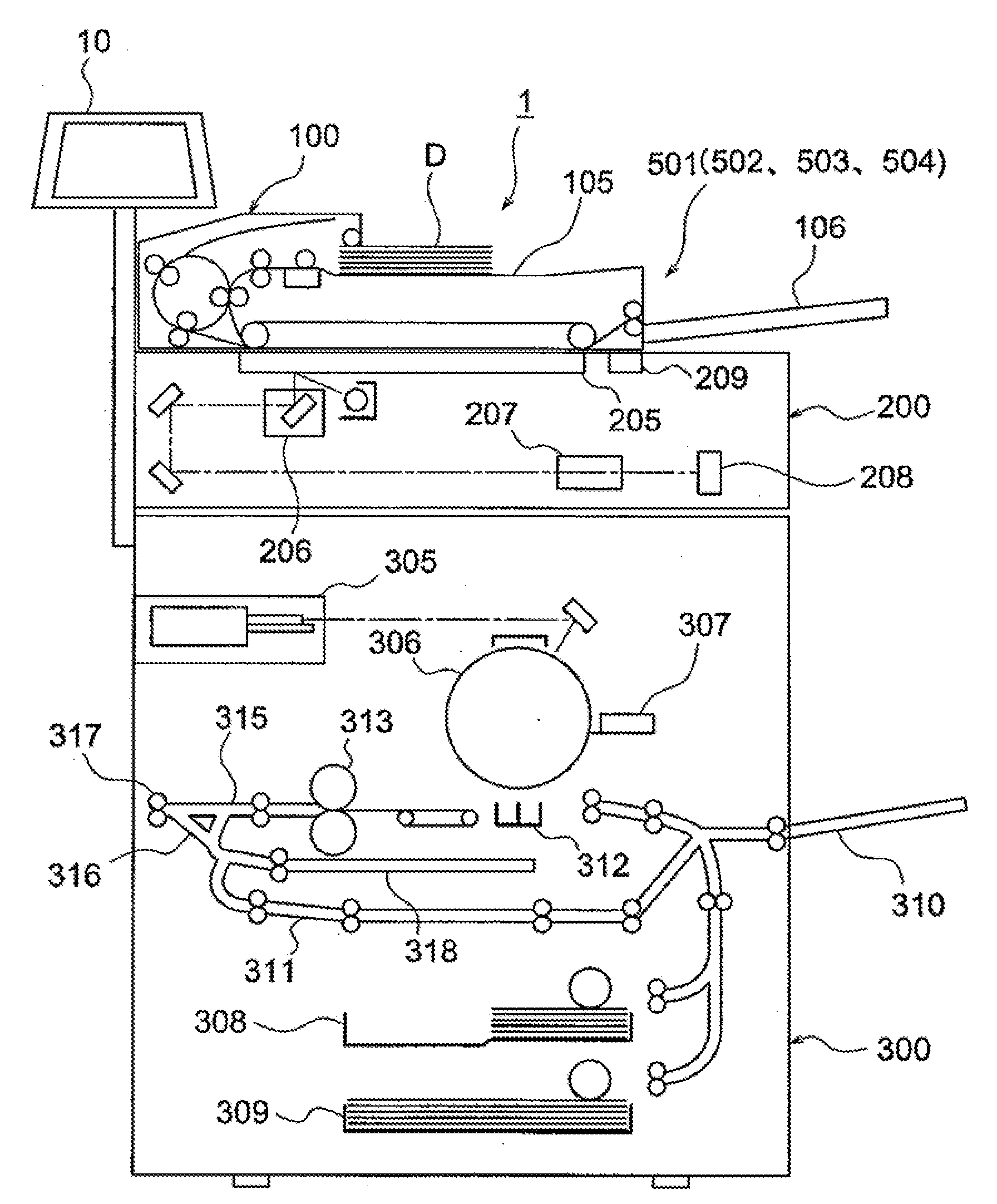
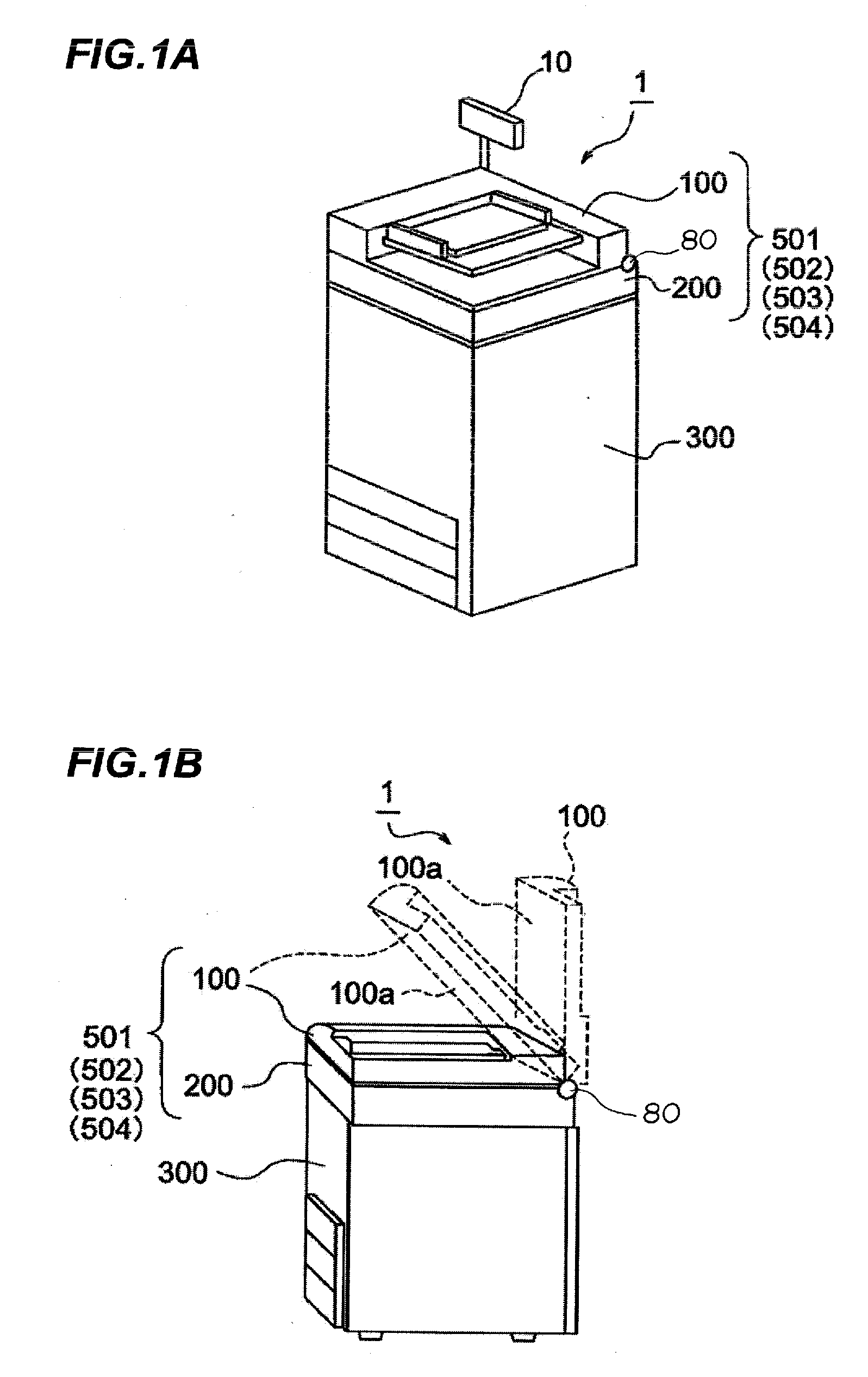
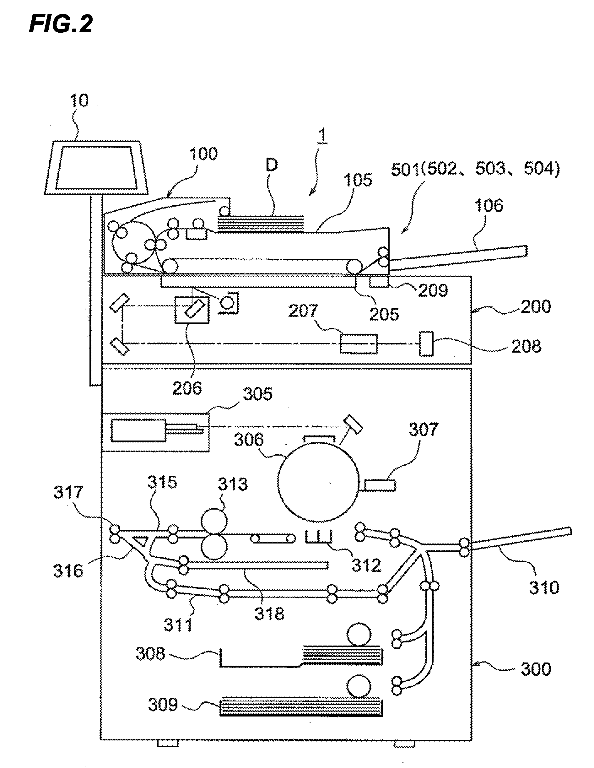
[0057]In FIGS. 1 to 3, the original conveying apparatus 100 is provided in the reading portion 200 to automatically open and close the reading portion 200. Plural motors 70 and 71 and the operation portion 10 are provided in the backside of the reading portion 200. The plural motors 70 and 71 are of the driving portion for opening and closing the original conveying apparatus 100. The stepping motors are used as the motors 70 and 71, and the stepping motors can freely change a speed and a rotation direction according to computation output of the opening and closing action controlling portion 14 (FIG. 4).
[0058]The opening and closing action controlling p...
second embodiment
[0081](Image Reading Apparatus of Second Embodiment)
[0082]The image reading apparatus 501 of the first embodiment is configured such that the rotation angular velocity ω1 of the motor 70 is matched with the rotation angular velocity ω2 of the motor 71. On the other hand, an image reading apparatus 502 according to a second embodiment is configured such that the rotation angular velocity ω1 of the motor 70 and the rotation angular velocity ω2 of the motor 71 are mutually matched with each other. Therefore, the image reading apparatus 502 of the second embodiment differs from the image reading apparatus 501 of the first embodiment in an opening and closing action controlling portion 114 and the flow of the control computation. Only the different points will be described with reference to FIGS. 8A and 8B.
[0083]FIG. 8A illustrates a block diagram for controlling the image forming apparatus and illustrates a signal flow in performing the control computation. FIG. 8B illustrates a flow ex...
third embodiment
[0095](Image Reading Apparatus of Third Embodiment)
[0096]In an image reading apparatus 503 according to a third embodiment, the rotation angular velocity ω1 of the motor 70 is matched with the rotation angular velocity ω2 of the motor 71, and the rotation angular velocity ω2 of the motor 71 is controlled in consideration of an inclination angular velocity ω3 of the original conveying apparatus 100, which is detected by the inclination detection sensor 11.
[0097]Therefore, in the image reading apparatus of the third embodiment, the variation in speed about the front-back direction axis L1 (FIG. 3) passing through the barycenter of the original conveying apparatus can be reduced in the original conveying apparatus during the opening and closing action.
[0098]FIGS. 9A and 9B illustrate the control of the image reading apparatus of the third embodiment. FIG. 9A partially illustrates a block diagram for controlling the image forming apparatus and illustrates a signal flow in performing the...
PUM
 Abstract
Description
Claims
Application Information
 - R&D
- Intellectual Property
- Life Sciences
- Materials
- Tech Scout
- Unparalleled Data Quality
- Higher Quality Content
- 60% Fewer Hallucinations
Browse by: Latest US Patents, China's latest patents, Technical Efficacy Thesaurus, Application Domain, Technology Topic, Popular Technical Reports.
© 2025 PatSnap. All rights reserved.Legal|Privacy policy|Modern Slavery Act Transparency Statement|Sitemap|About US| Contact US: help@patsnap.com


