Cord protector for power tools

Inactive Publication Date: 2009-01-01
BLACK & DECKER INC
View PDF22 Cites 25 Cited by
  • Summary
  • Abstract
  • Description
  • Claims
  • Application Information

AI Technical Summary

Benefits of technology

[0005]To isolate the power cord conductors or connections from the high forces imposed by jerking the power cord, the power cord according to the present disclosure is installed in the tool housing with a small service loop, or extra length of cable, between the cord clamp and the portion of the tool housing that secures the cord protector. A crimp-on device is installed on the power cord cable next to the cord protector. When the cord is subjected to jerking, the cable moves axially relative to the cord protector. As the cable moves, the crimp-on device compresses the extended end of the cord protector absorbing energy and reducing the forces transmitted to the cord set conductors or connections that are disposed within the housing.

Problems solved by technology

A common field failure with heavier portable power tools, such as portable saws, is a separation of the power cord from the tool due to an impulse load, or jerk, applied to the cord.

Method used


Image

  • Cord protector for power tools
  • Cord protector for power tools
  • Cord protector for power tools

Examples


Embodiment Construction

[0028]The following description is merely exemplary in nature and is not intended to limit the present disclosure, application, or uses. It should be understood that throughout the drawings, corresponding reference numerals indicate like or corresponding parts and features.

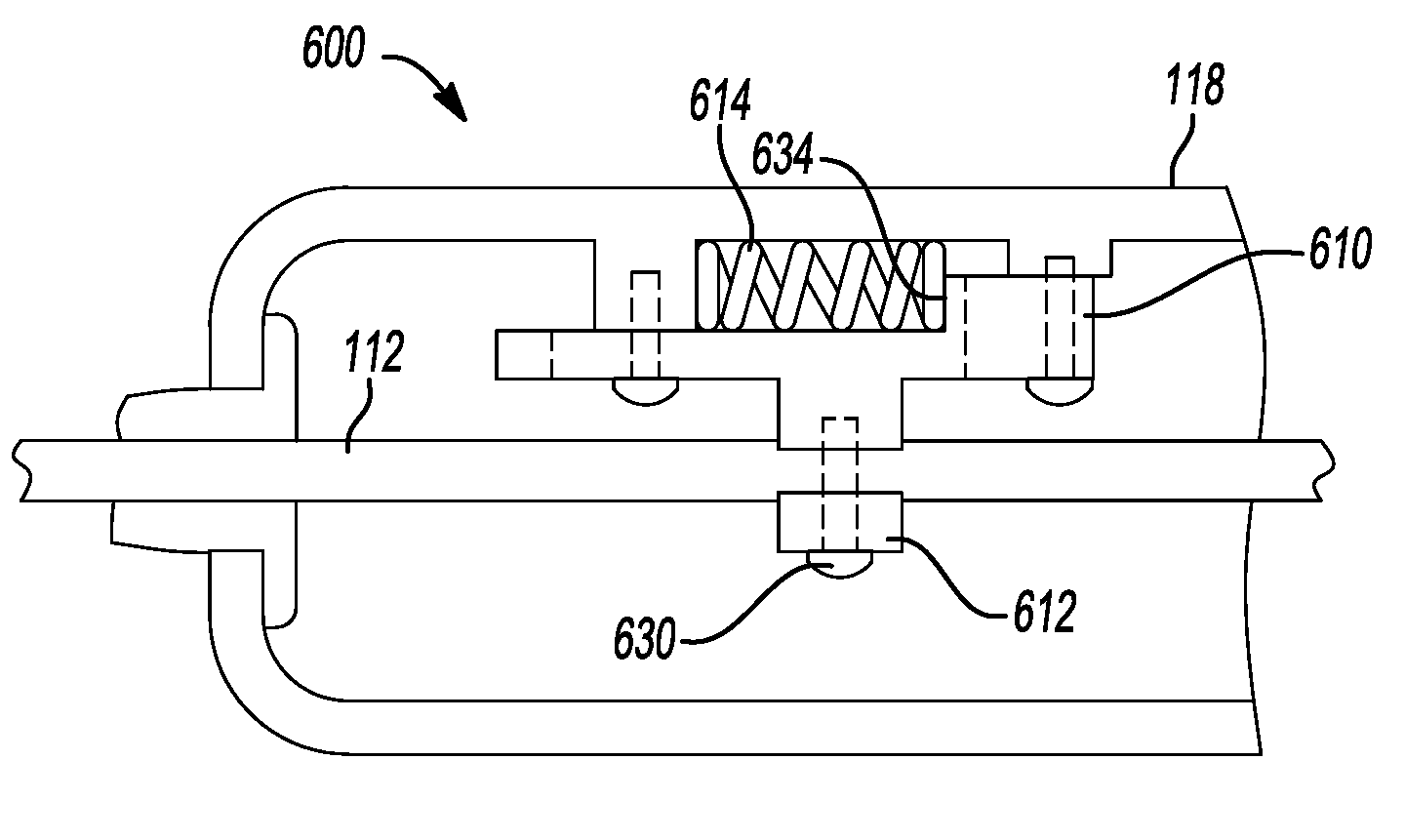
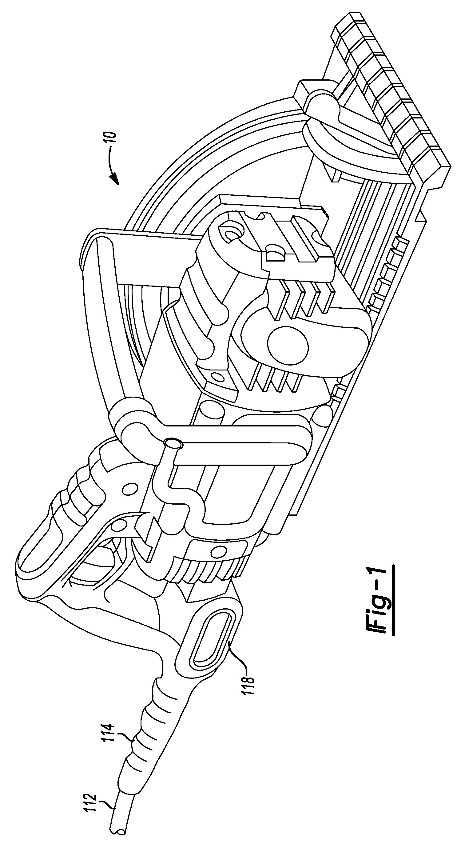
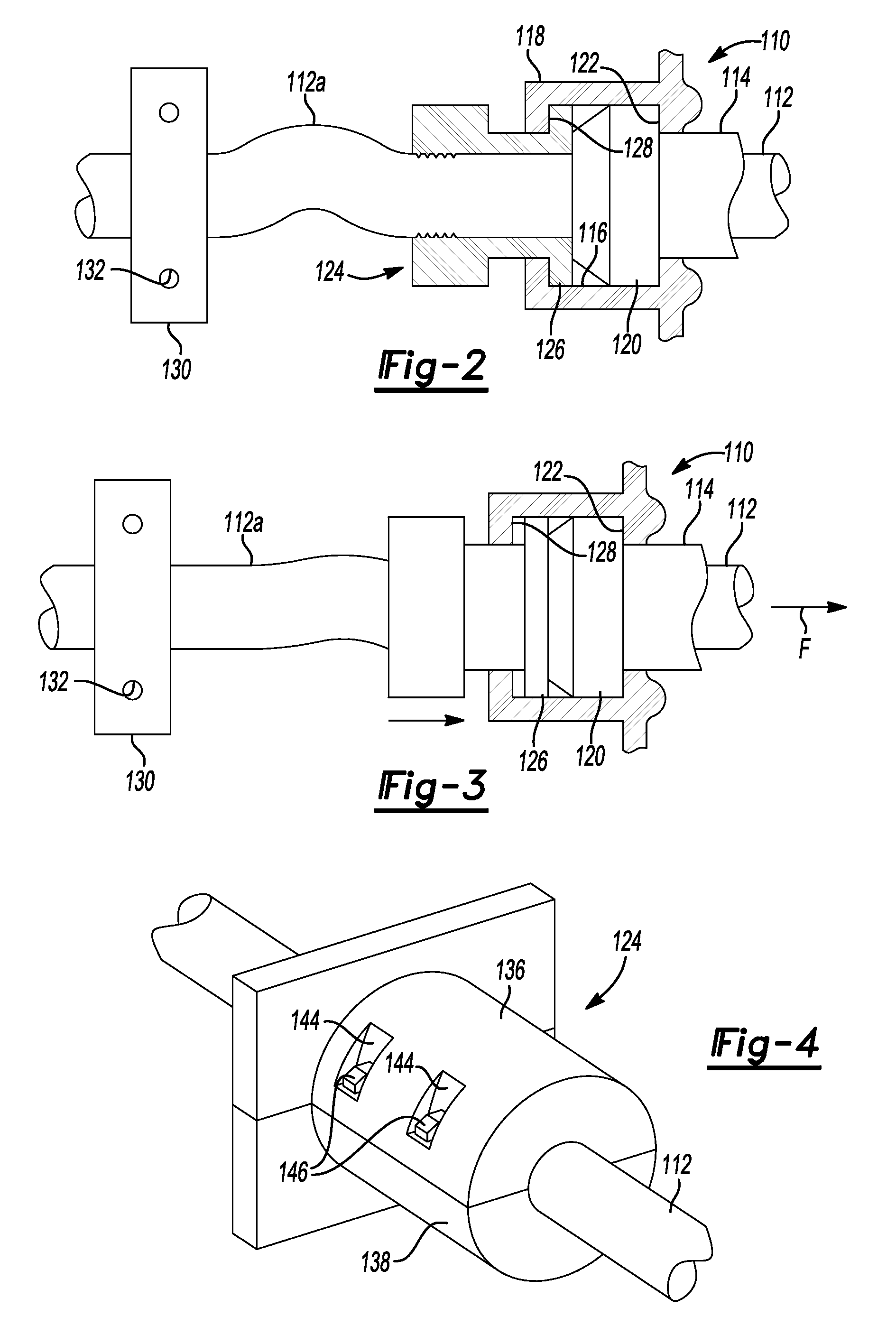
[0029]With reference to FIGS. 1 and 2, an exemplary power tool 10 is shown having a cord set load protector device 114 for preventing high forces imposed on a power cord 112 from impacting the connections of the cord 112 to the electrical power tool 10. As illustrated in FIG. 1, the power tool 10 includes a cord 112 and a cord protector 114 extending from the rear end of the tool. The cord protector 114 is mounted within a recess 116 provided in the power tool housing 118. The recess 116 can be square or round in cross-section and defines a cavity therein for receiving a radially extending flange portion 120 of the elastomeric cord protector 114. The radial extending flange portion 120 is disposed against a should...


PUM


Abstract

A power tool having a housing, a motor disposed in the housing, a power cord connected to the motor, and a cord protector operably engaging the power cord for movement therewith. The cord protector comprises a cam follower bracket having a camming slot sized to receive a cam follower. The cam follower bracket being biased into an initial position and exerting a biasing force upon the power cord in response to a load being applied to the power cord.

Description

CROSS-REFERENCE TO RELATED APPLICATIONS[0001]This application is a continuation in part of U.S. application Ser. No. 11 / 860,989 filed on Sep. 25, 2007, which claims the benefit of U.S. Provisional Application No. 60 / 863,467 filed on Oct. 30, 2006, the disclosure of which is incorporated herein by reference.FIELD[0002]The present disclosure relates to various improvements for power tools, and particularly to a cord set load protector.BACKGROUND AND SUMMARY[0003]The statements in this section merely provide background information related to the present disclosure and may not constitute prior art.[0004]A common field failure with heavier portable power tools, such as portable saws, is a separation of the power cord from the tool due to an impulse load, or jerk, applied to the cord. This can occur when the tool is dropped while the plug end of the power cord is secured, or when a user carries the tool or lowers it from floor to floor or down a ladder by holding the power cord.[0005]To i...

Claims


Application Information

Patent Timeline
IPC IPC(8): H01R13/58
CPCB25F5/00H02G15/007H01R13/585B27B5/29
Inventor PUZIO, DANIELOPSITOS, ROBERTNICKELS, JR., RICHARD C.
Owner BLACK & DECKER INC
Why Eureka
Try Eureka