Duckbill seal with fluid drainage feature

a technology of fluid drainage and duckbill, which is applied in the field of seal assemblies, can solve the problems of difficulty in maintaining internal gas pressure and obscure the view of surgeons, and achieve the effects of promoting fluid movement, fluid movement, and fluid movemen

Active Publication Date: 2009-01-01
CILAG GMBH INT
View PDF99 Cites 180 Cited by
  • Summary
  • Abstract
  • Description
  • Claims
  • Application Information

AI Technical Summary

Benefits of technology

[0008]Trocars are generally provided having one or more seal assemblies for selectively promoting movement of fluid away from a central portion of the seal assemblies. In one embodiment, a seal assembly for use in a trocar assembly is provided and includes a seal body configured to selectively open the seal assembly in response to an object being inserted into the seal body. In an exemplary embodiment, an inner surface of the seal body is configured to selectively promote movement of fluid away from a central portion of the seal body toward a peripheral portion of the seal body. In one embodiment, the central portion of the seal body is located at a more proximal position than the peripheral portion of the seal body. Further, the inner surface of the seal body can be formed by any number of geometric shapes, but in two exemplary embodiments, the inner surface of the seal body extends in a substantially linear manner from the central portion to the peripheral portion, or alternatively, the inner surface of the seal body extends in a substantially arcuate manner from the central portion to the peripheral portion. In one embodiment, the seal assembly is a duckbill seal assembly.
[0009]In another embodiment of a seal assembly for use in a trocar assembly, a seal body having a longitudinal axis extending therethrough and a transverse plane substantially perpendicular to the longitudinal axis is provided, as is a plurality of opposed seal elements extending distally at an acute angle with respect to the transverse plane from a proximal end of the seal body. The opposed seal elements can include inner and outer surfaces that meet at a seal face located at a distal end of the seal body, and further, the opposed seal elements can be configured to selectively open and substantially close the seal face. In an exemplary embodiment, the inner surfaces of the seal elements can be configured to selectively promote movement of fluid away from a central portion of the seal elements toward a peripheral portion of the seal elements at the seal face. In one embodiment, the central portion of each of the inner surfaces of the seal elements is located at a more proximal position than the peripheral portion of the seal elements at the seal face. Further, the inner surfaces of each of the seal elements can be formed by any number of geometric shapes, but in two exemplary embodiments, the inner surfaces extend in a substantially linear manner from the central portion to the peripheral portion, or alternatively, the inner surfaces of each of the seal elements extend ...

Problems solved by technology

However, it can be difficult to maintain the internal gas pressure because during the course of the procedure instruments are typically passed into and out of the troc...

Method used


Image

  • Duckbill seal with fluid drainage feature
  • Duckbill seal with fluid drainage feature
  • Duckbill seal with fluid drainage feature

Examples


Embodiment Construction

[0025]Certain exemplary embodiments will now be described to provide an overall understanding of the principles of the structure, function, manufacture, and use of the devices disclosed herein. One or more examples of these embodiments are illustrated in the accompanying drawings. Those skilled in the art will understand that the devices specifically described herein and illustrated in the accompanying drawings are non-limiting exemplary embodiments and that the scope of the present invention is defined solely by the claims. The features illustrated or described in connection with one exemplary embodiment may be combined with the features of other embodiments. Such modifications and variations are intended to be included within the scope of the present invention.

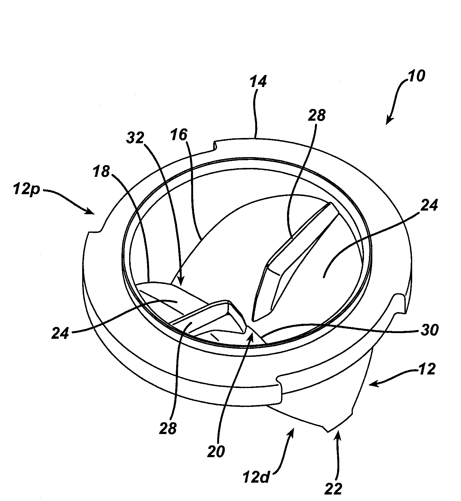
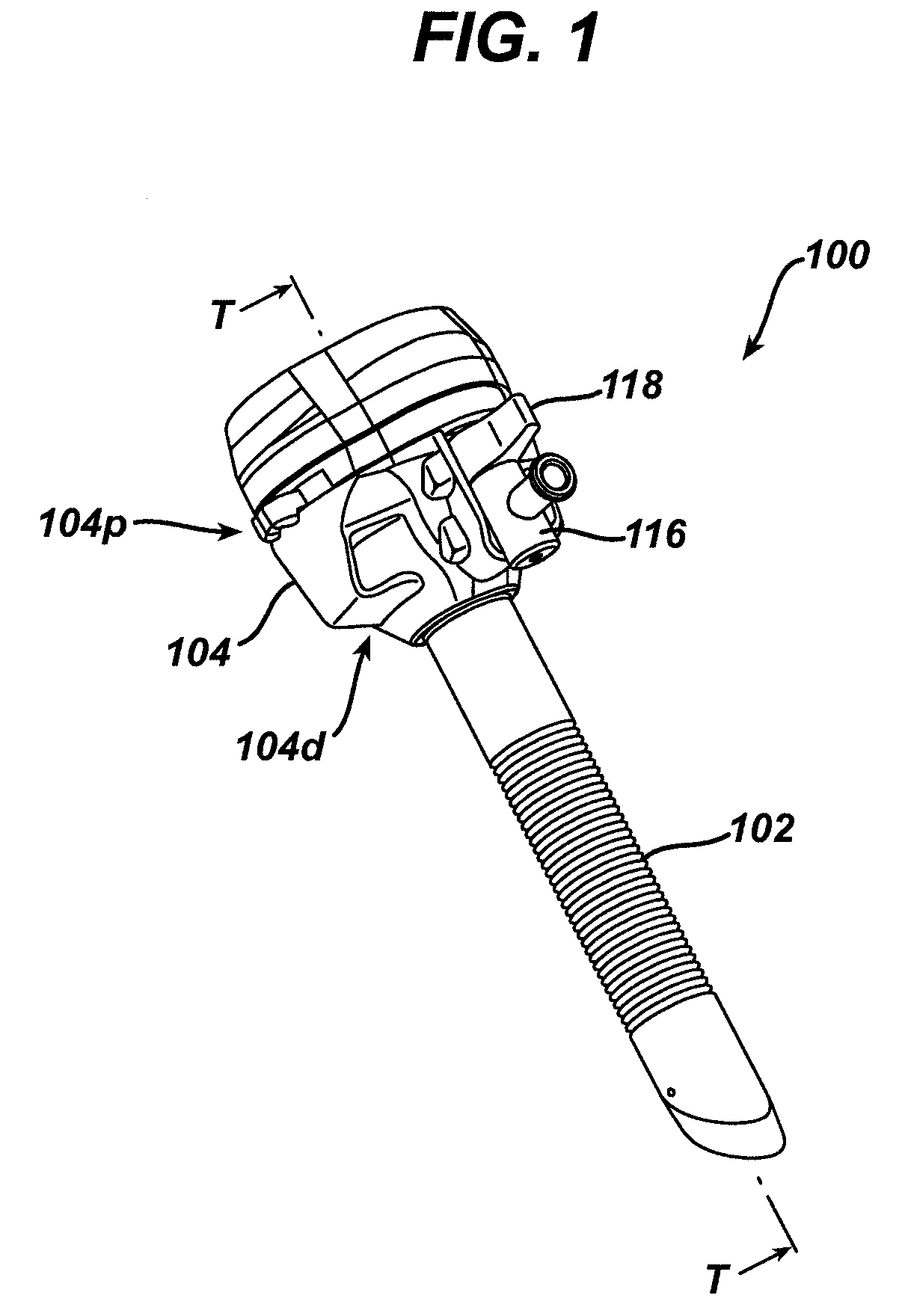
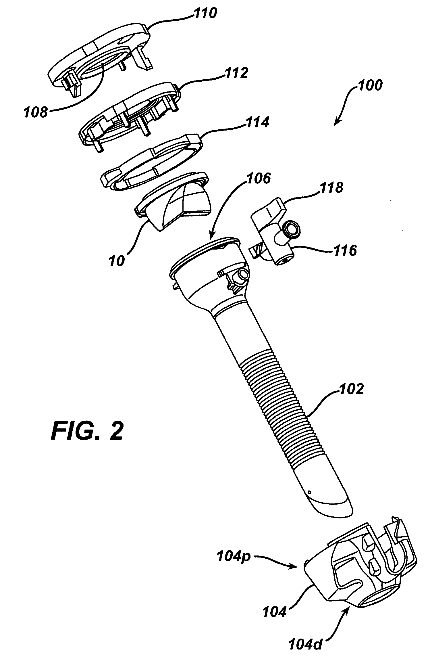
[0026]The trocar described herein includes a seal assembly that is constructed to provide for selective movement of fluid away from a central portion of a seal body toward a peripheral portion of the seal body. This selectiv...


PUM


Abstract

Seal assemblies, generally for use in trocar assemblies, are provided for selectively promoting movement of fluid away from a central portion of the seal assemblies. In one exemplary embodiment, an inner surface of a seal body of the seal assembly is configured to selectively promote such movement of fluid away from the central portion of the seal body toward a peripheral portion of the seal body. While various configurations, geometries, and dimensions are discussed, one example of such a configuration includes locating a central portion of the seal body at a more proximal position than a peripheral portion of the seal body.

Description

FIELD OF THE INVENTION[0001]This application relates to trocar assemblies, and more particularly, to seal assemblies often used in trocar assemblies.BACKGROUND OF THE INVENTION[0002]Surgical procedures often require a surgeon to gain access to a cavity in a patient's body. Generally, when such a procedure is required, an incision is made in an exterior wall of the cavity and an instrument is inserted into the working channel created by the incision. One common instrument used in such a procedure is a trocar assembly. Trocar assemblies include a variety of components, but generally can include a trocar cannula, a trocar obturator, and a trocar housing. In many designs, in order to access the body cavity, the trocar cannula is directed through the skin and the trocar obturator is inserted through an interior lumen defined by the cannula. The trocar obturator is then used to penetrate the skin, which has often already had an incision made in it with a scalpel or similar device, and acc...

Claims


Application Information

Patent Timeline
IPC IPC(8): A61B17/34
CPCA61B1/00137A61B1/126A61B2017/3437A61B19/38A61B17/3462A61B90/40Y10T137/7882
Inventor FRANER, PAUL T.GILKER, THOMAS A.
Owner CILAG GMBH INT
Why Eureka
Try Eureka