Apparatus for Driving Clothes Press Irons and Clothes Press Finishing Machine Using the Same

Inactive Publication Date: 2009-01-08
SANKOSHA ENGINEERING CO LTD
View PDF8 Cites 2 Cited by
  • Summary
  • Abstract
  • Description
  • Claims
  • Application Information

AI Technical Summary

Benefits of technology

[0018]A reason why this system is applied consists in the fact that a parallel motion can be easily attained because the main body 6a has six articulations.
[0039]Additionally, the finishing machine of this invention can eliminate an expensive guide component and does not accompany with any sliding structure. Accordingly, in accordance with this invention, its price can be made less-expensive and a stable operation can be easily maintained for a long period of time.

Problems solved by technology

Thus, in accordance with this prior art, there was a certain restriction for reducing the depth length of the finishing machine, its installation space was required wide and there was a certain restriction about its small-sized formation or space saving and the like.
In addition, since the driving apparatus disclosed in Patent Document 1 was installed below the torso, equipment such as pipings could not be freely installed below the torso.
Due to this fact, the prior art finishing machine had a problem that its increased weight and large-sized driving device cannot be avoided.
Accordingly, in accordance with this prior art, there occurred a problem that the component cost is increased and the product price becomes easily expensive.
Further, in accordance with this prior art, there occurred a problem that the engaged location of the component parts is worn out and a stable operation of long period of time is hardly assured.

Method used


Image

  • Apparatus for Driving Clothes Press Irons and Clothes Press Finishing Machine Using the Same
  • Apparatus for Driving Clothes Press Irons and Clothes Press Finishing Machine Using the Same
  • Apparatus for Driving Clothes Press Irons and Clothes Press Finishing Machine Using the Same

Examples


Embodiment Construction

[0051]The best mode for carrying out this invention will be described as follows.

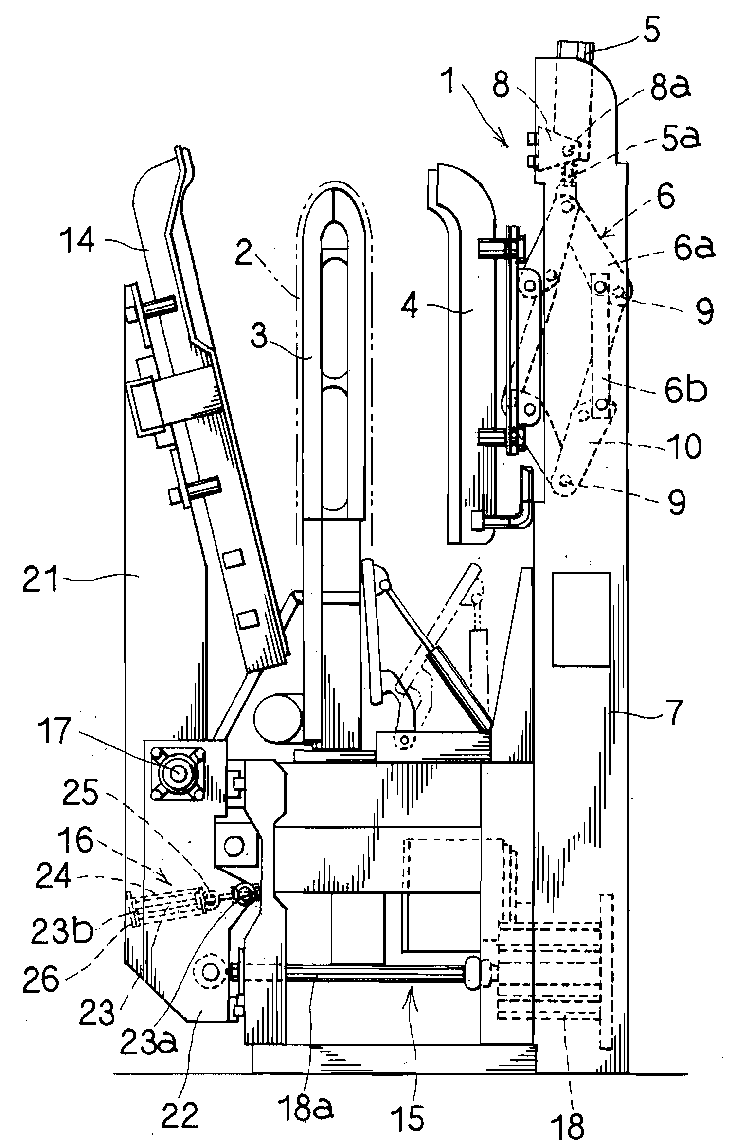
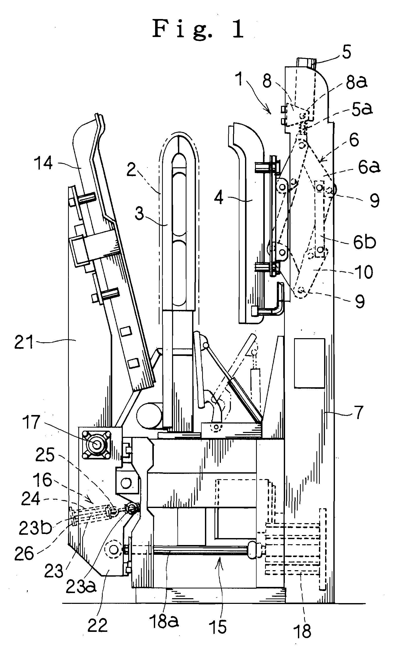
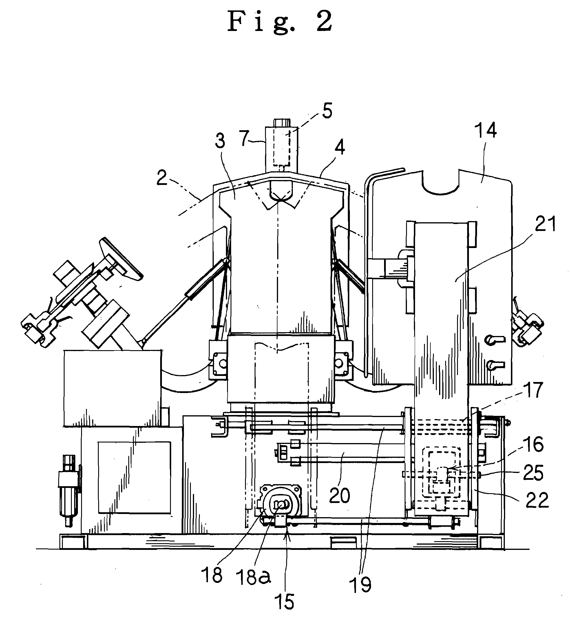
[0052]As shown in FIG. 1 and the like, the driving device 1 of this invention in its preferred embodiment is realized by a clothes press iron 4 at a rear side for pressing the rear side of a torso 3 for putting on clothes 2 and press finishing the rear surface of clothes 2.

[0053]Thus, the driving device 1 of this invention is formed by a vertical-oriented cylinder device 5 oscillating in a forward or rearward direction of a torso 3 and a cylinder device 6 fixed to the extremity end of a rod 5a of this cylinder device 5 to convert an extending or retracting operation of the rod 5a into an advancing or retracting operation of the clothes press iron 4 at the rear side.

[0054]The aforesaid cylinder device 5 is fixed in the upper part of a supporting column 7 upright just at a rear side of the torso 3 in this preferred embodiment with the rod 5a being faced downward. Reference numeral 8 denotes a fixing membe...


PUM


Abstract

This invention relates to a driving device for the clothes press iron 4 or 14 for pressing a front side or rear side of the torso 3 for putting on the clothes 2 and press finish the clothes 2. The driving device of this invention is formed by the vertical-oriented cylinder device 5 oscillated in a forward or rearward direction of the torso 3 and the link device 6 fixed at the extremity end of the rod 5a of this cylinder device 5 to convert an extending or retracting operation of the rod 5a into an advancing or retracting operation of the clothes press iron 4 or 14. The main body 6a of the link device 6 is preferably set such that six link members 10 are connected in a substantial hexagonal shape as seen from the side of the torso 3 by the axle member 9 along a lateral direction of the torso 3. In accordance with this invention, it is possible to restrict a depth size of the finishing machine and a compact-sized finishing machine and its space saving can be attained.

Description

BACKGROUND OF INVENTION [0001]1. Field of the Invention[0002]This invention relates to an apparatus for driving press irons for press finishing clothes such as shirts or jackets or the like while being put on a torso, and more particularly an apparatus for driving press irons and a press finishing machine for clothes using the same.[0003]2. Description of the Prior Art[0004]This type of driving apparatus of the prior art is usually constructed in such a way that a rod is arranged to extend or retract in a forward or rearward direction of a torso (refer to U.S. Pat. No. 4,634,030, hereinafter called as “Patent Document 1”, for example).[0005]In addition, as this type of driving apparatus, it has already been known as well to provide a structure for extending or retracting press irons in response to an extending or retracting operation of a rod (refer to U.S. Pat. No. 6,758,377, hereinafter called as “Patent Document 2”, for example).[0006]Accordingly, in the case of the driving appar...

Claims


Application Information

Patent Timeline
IPC IPC(8): D06C15/00D06F73/00D06F71/00
CPCD06F71/20D06F71/18D06F71/32
Inventor UCHIKOSHI, MITSUYUKI
Owner SANKOSHA ENGINEERING CO LTD
Why Eureka
Try Eureka