Power transmission device, electronic instrument, and waveform monitoring circuit

a technology of waveform monitoring and transmission device, which is applied in the direction of reverse polarity correction, inductance, safety/protection circuit, etc., can solve the problems of load state detection accuracy not being improved to a satisfactory level and waveform being reduced

Active Publication Date: 2009-01-08
SAMSUNG ELECTRONICS CO LTD
View PDF17 Cites 54 Cited by
  • Summary
  • Abstract
  • Description
  • Claims
  • Application Information

AI Technical Summary

Benefits of technology

[0012]a first rectifier circuit having a limiter function, the first rectifier circuit including a first resistor that is a current-limiting resistor provided between a coil end node where a coil end signal of the primary coil is generated and a first monitoring node where a waveform-monitoring first induced voltage signal is generated, performing a limiter operation that clamps the first induced voltage signal at a high-potential-side power supply voltage, performing a half-wave rectification of the first induced voltage signal, and outputting the first induced voltage signal to a power transmission control device of the power transmission device; and

Problems solved by technology

Therefore, the waveform is reduced due to voltage division, whereby the load state detection accuracy cannot be improved to a satisfactory level.

Method used


Image

  • Power transmission device, electronic instrument, and waveform monitoring circuit
  • Power transmission device, electronic instrument, and waveform monitoring circuit
  • Power transmission device, electronic instrument, and waveform monitoring circuit

Examples


Embodiment Construction

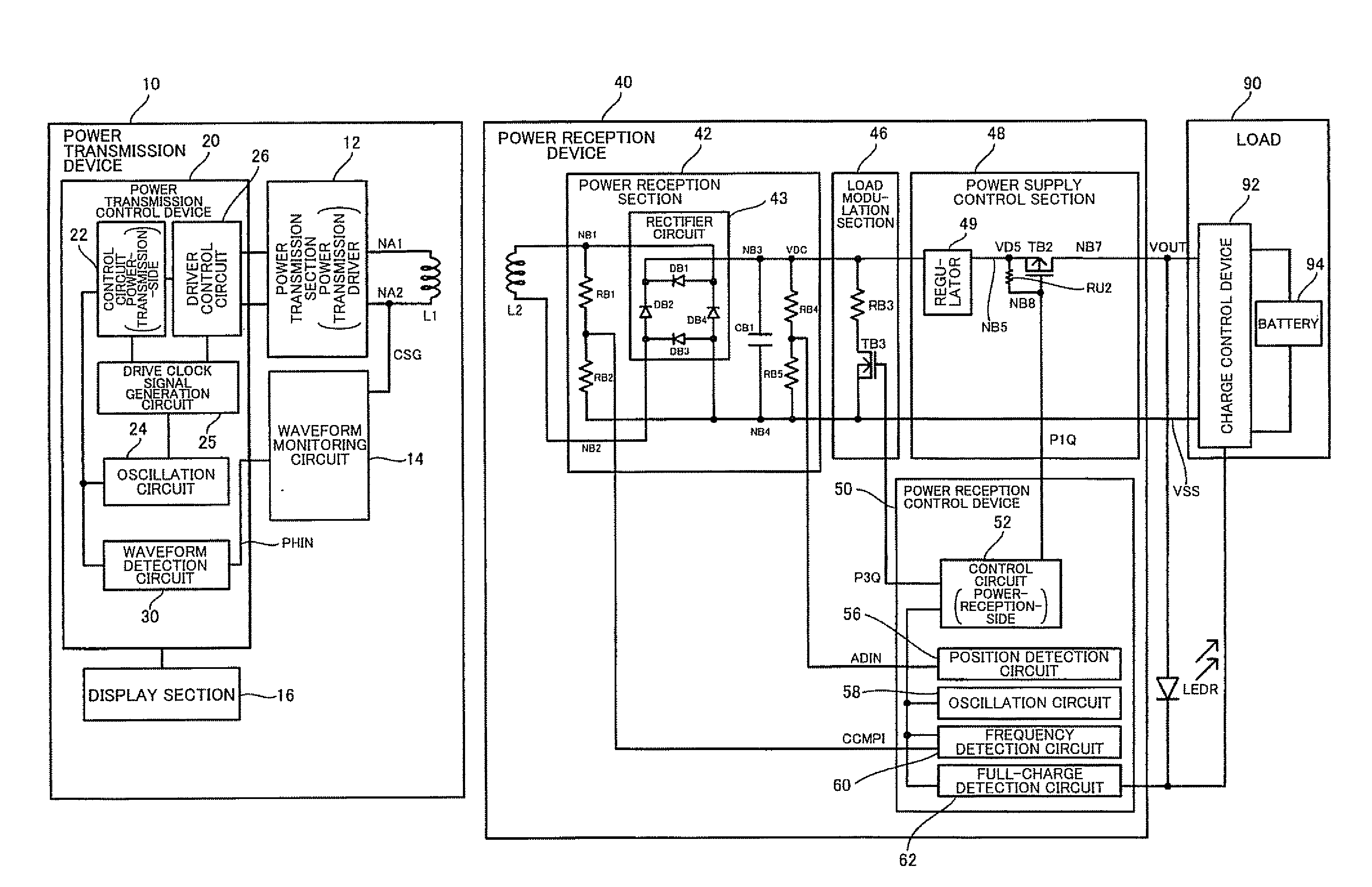
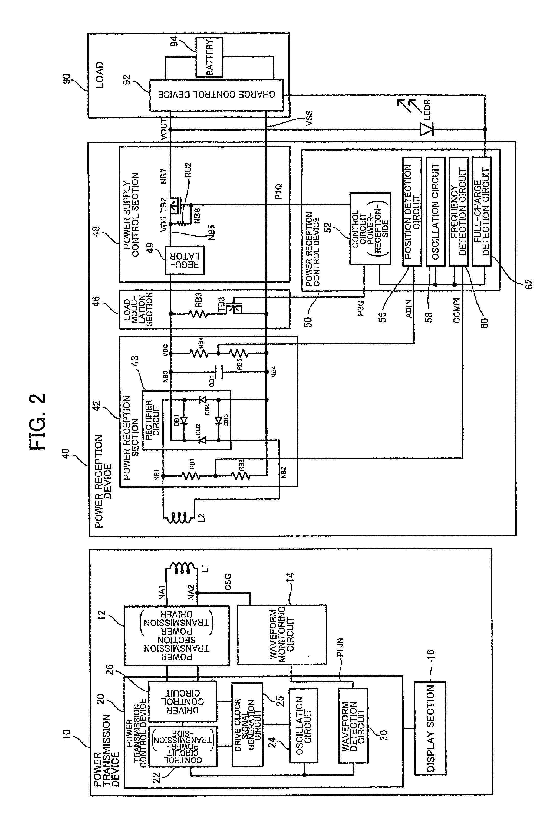
[0039]Several aspects of the invention may provide a power transmission device including a waveform monitoring circuit suitable for a non-contact power transmission system, an electronic instrument, and the like.

[0040]According to one embodiment of the invention, there is provided a power transmission device included in a non-contact power transmission system that transmits power to a power reception device by electromagnetically coupling a primary coil and a secondary coil to transmit power to a load of the power reception device, the power transmission device comprising:

[0041]a waveform monitoring circuit that generates and outputs a waveform-monitoring induced voltage signal based on a coil end signal of the primary coil; and

[0042]a power transmission control device that controls a power transmission driver that drives the primary coil, the power transmission control device receiving the waveform-monitoring induced voltage signal and detecting a waveform of the induced voltage si...


PUM


Abstract

A power transmission device of a non-contact power transmission system includes a waveform monitoring circuit that generates and outputs a waveform-monitoring induced voltage signal based on a coil end signal of a primary coil, and a power transmission control device that controls a power transmission driver that drives the primary coil, the power transmission control device receiving the waveform-monitoring induced voltage signal and detecting a change in waveform of the induced voltage signal to detect a power-reception-side load state. The waveform monitoring circuit includes a first rectifier circuit having a limiter function, the first rectifier circuit including a current-limiting resistor provided between a coil end node where the coil end signal of the primary coil is generated and a monitoring node where the waveform-monitoring induced voltage signal is generated, performing a limiter operation that clamps the induced voltage signal at a high-potential-side power supply voltage, and subjecting the induced voltage signal to half-wave rectification.

Description

[0001]Japanese Patent Application No. 2007-175874 filed on Jul. 4, 2007 and Japanese Patent Application No. 2008-117439 filed on Apr. 28, 2008, are hereby incorporated by reference in their entirety.BACKGROUND OF THE INVENTION[0002]The present invention relates to a power transmission device, an electronic instrument, a waveform monitoring circuit, and the like.[0003]In recent years, non-contact power transmission (contactless power transmission) that utilizes electromagnetic induction to enable power transmission without metal-to-metal contact has attracted attention. As application examples of non-contact power transmission, charging a portable telephone, charging a household appliance (e.g., telephone handset), and the like have been proposed.[0004]As related-art non-contact power transmission technology, a power transmission device has been known which implements data transmission from a power reception device (secondary side) to a power transmission device (primary side) by mea...

Claims


Application Information

Patent Timeline
Patent Type & Authority Applications(United States)
IPC IPC(8): H02J17/00
CPCH02J7/0011H02J7/045H02J7/025H02J7/0034H02J7/04H02J7/00711H02J50/80H02J50/90H02J50/12H02J7/007182H02J50/60H02J7/00
Inventor JIN, MIKIMOTOKAMIJO, TAKAHIROYODA, KENTAROSOGABE, HARUHIKOONISHI, KOTAIISAKA, KEN
Owner SAMSUNG ELECTRONICS CO LTD
Why Eureka
Try Eureka