Directional fault current indicator

a fault current indicator and directional technology, applied in the direction of fault location, emergency protective circuit arrangement, instruments, etc., can solve the problems of troublesome use of conventional non-directional fault indicators to determine fault location, complex fault location task in networked power distribution systems, and difficulty in detecting and locating faults

Active Publication Date: 2009-01-08
THOMAS & BETTS INT INC
View PDF26 Cites 57 Cited by
  • Summary
  • Abstract
  • Description
  • Claims
  • Application Information

AI Technical Summary

Problems solved by technology

However, the fault location task is complicated in networked power distribution systems, such as urban and underground power distribution networks, because the direction of power flow through a particular line can change over time in response to load and source changes.
Since power flow direction at any time is not known, it is problematic to use conventional non-directional fault indicators to determine fault location.
Other problems are encountered in detecting and locating faults in an underground network.
Back fed current complicates fault detection and location.
Network protector operation may be inconsistent and some protectors may not close after a fault has been repaired.
This failed operation may leave segments of the network unenergized and unreported.
The relatively short distance and attendant interference between conductors in the underground network also complicates fault detection.

Method used


Image

  • Directional fault current indicator
  • Directional fault current indicator
  • Directional fault current indicator

Examples


Embodiment Construction

[0016]Before describing in detail the particular method and apparatus related to a directional fault current indicator, it should be observed that the present invention resides primarily in a novel and non-obvious combination of elements and process steps. So as not to obscure the disclosure with details that will be readily apparent to those skilled in the art, certain conventional elements and steps have been presented with lesser detail, while the drawings and the specification describe in greater detail other elements and steps pertinent to understanding the invention.

[0017]The following embodiments are not intended to define limits as to the structure or method of the invention but only to provide exemplary constructions. The embodiments are permissive rather than mandatory and illustrative rather than exhaustive.

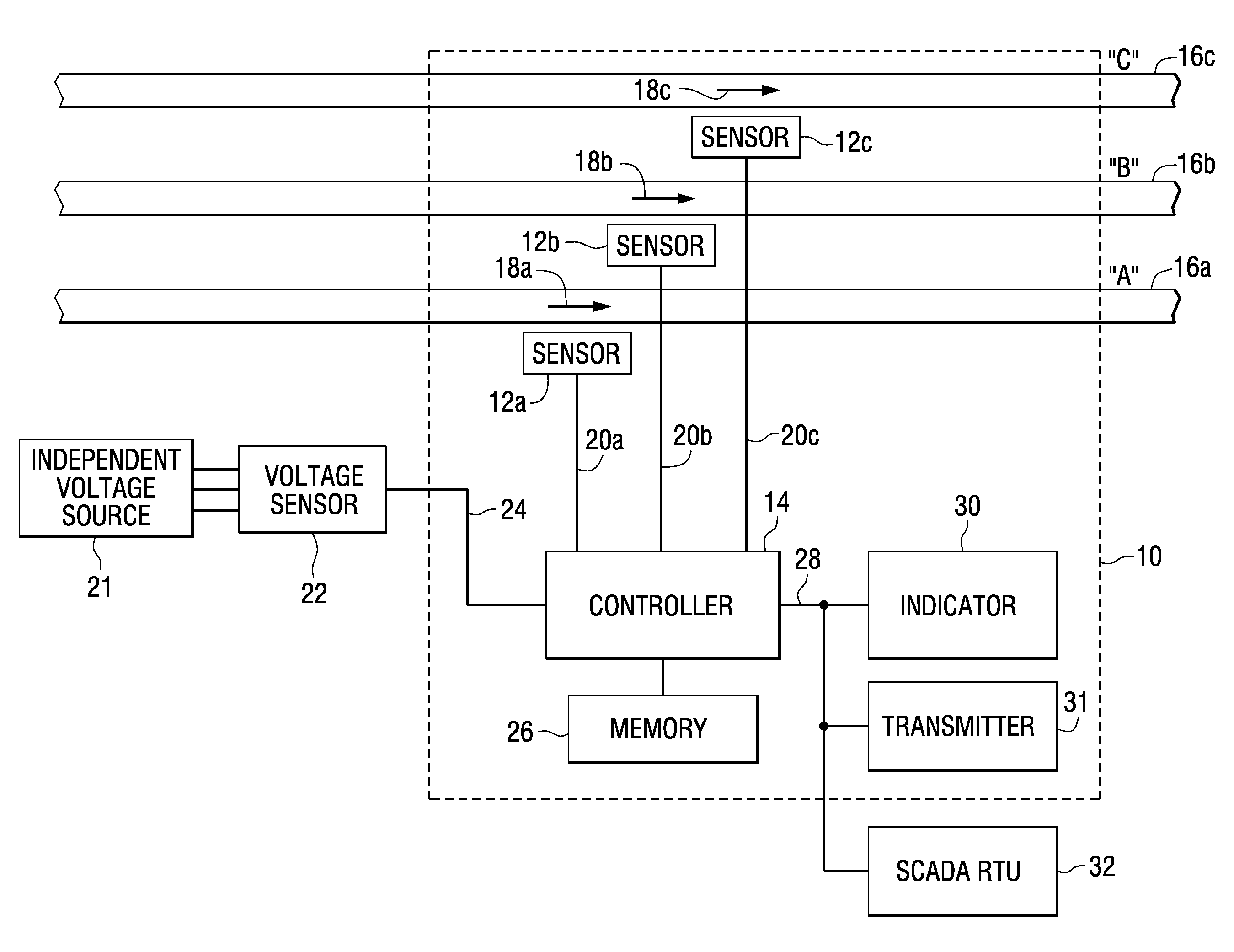
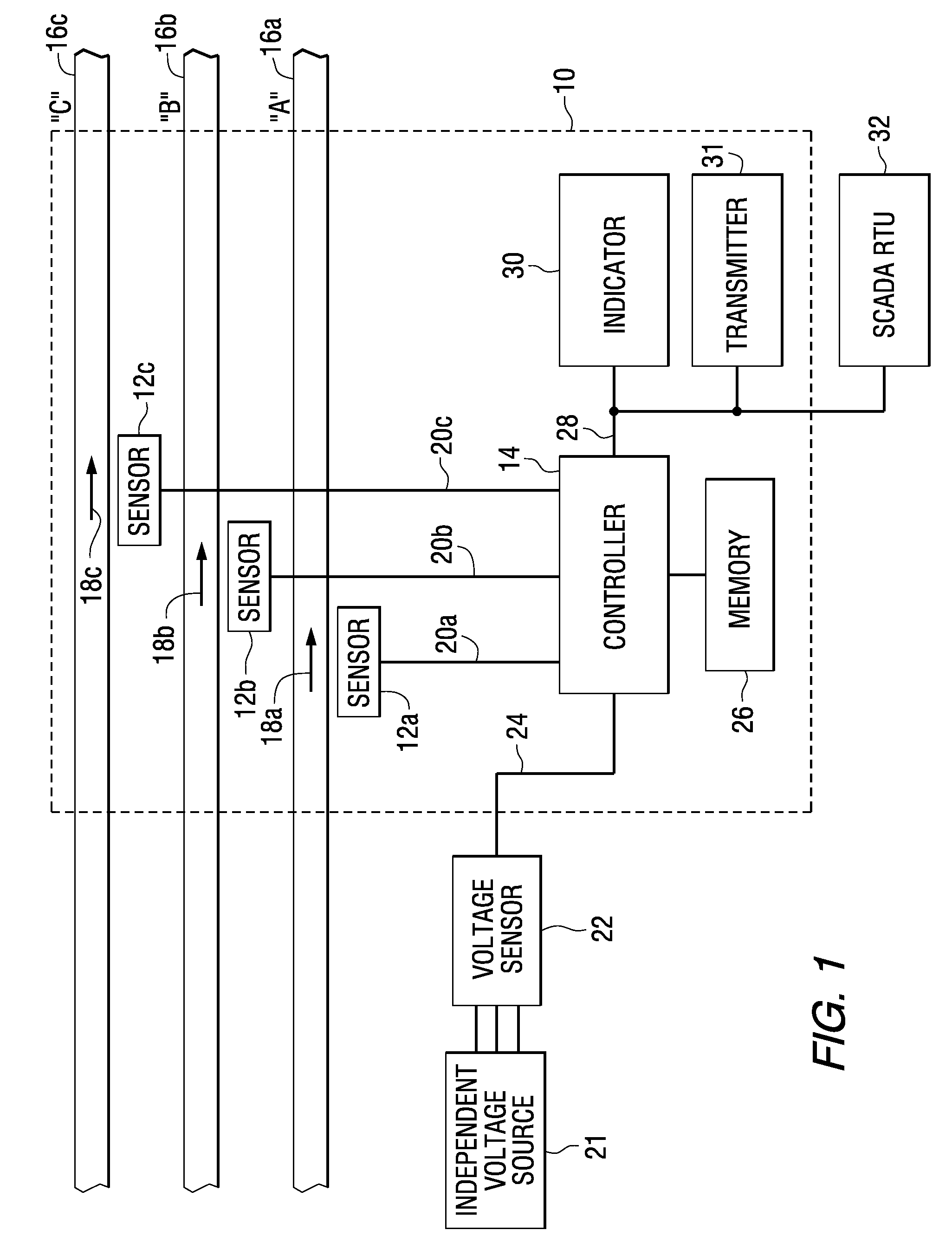
[0018]The directional fault current indicator of the present invention detects the occurrence of and direction to a fault on a power system grid (including a networked...


PUM


Abstract

A method for identifying a fault condition associated with a power line conductor of an electrical power distribution network. The method comprises determining a load current carried by the conductor is above a minimum load current, determining a learned phase angle relationship between the load current and a source signal, determining a load current magnitude, determining a real-time phase angle relationship between the load current and the source signal and indicating a fault condition when the real-time phase angle relationship is within a predetermined number of angular degrees of the learned phase angle relationship and when the load current magnitude exceeds a fault-indicating current.

Description

REFERENCE TO RELATED APPLICATIONS[0001]This application claims the benefit, under 35 U.S.C. 119(e), of the provisional patent application entitled Directional Fault Circuit Indicator filed on Jul. 3, 2007 and assigned application Ser. No. 60 / 947,751.[0002]FIELD OF THE INVENTION[0003]This invention relates generally to the field of fault detection in electrical power distribution networks.BACKGROUND OF THE INVENTION[0004]The three power-supplying phase feeders (conductors) are monitored to detect electrical fault conditions on the distribution lines of an electrical power distribution network (grid). To clear or repair the faults, such as short circuits, it is important to first determine the fault location. In conventional overhead distribution systems there is a normal power flow direction, with power flow in the opposite direction (reverse power flow) only for contingency purposes. Reverse direction power flow is always known by the system operations staff and accounted for in sys...

Claims


Application Information

Patent Timeline
Patent Type & Authority Applications(United States)
IPC IPC(8): G01R31/08G01R31/00
CPCG01R31/088H02H3/382H02H3/081
Inventor VARGHAI, MEHRIDOMO, JAMES FRANCIS
Owner THOMAS & BETTS INT INC
Why Eureka
Try Eureka