Obstacle detection apparatus

a technology for obstacle detection and detection apparatus, which is applied in the direction of measurement devices, vehicle components, instruments, etc., can solve the problems of increasing error detection, difficulty in improving the performance of obstacle detection apparatus, and the ultrasonic sensor may receive a reflected ultrasonic wave coming from an undesired direction, so as to reduce the undetectable area and restrict error detection

Inactive Publication Date: 2009-01-08
DENSO CORP
View PDF1 Cites 48 Cited by
  • Summary
  • Abstract
  • Description
  • Claims
  • Application Information

AI Technical Summary

Benefits of technology

[0018]According to the above obstacle detection apparatus, it is possible to detect both a relatively distance obstacle and a relatively nearby obstacle. It is possible to restrict error detection in detecting a relatively distance obstacle. It is possible to reduce an undetectable area in detecting a relatively nearby obstacle.
[0020]According to the above obstacle detection apparatus, it is possible to detect both a relatively distance obstacle and a relatively nearby obstacle. It is possible to restrict error detection in detecting a relatively distance obstacle. It is possible to reduce an undetectable area in detecting a relatively nearby obstacle.

Problems solved by technology

Therefore, it has been difficult to improve performance of an obstacle detection apparatus required in both the above cases.
However, when an ultrasonic sensor having a low directivity is used for detecting an obstacle located distant from the vehicle, the ultrasonic sensor may receive a reflected ultrasonic wave coming from an undesired direction.
As a result, error detection increases, and it becomes difficult to increase a sensing distance.
However, the use of the ultrasonic sensor with a high directivity increases an undetectable area around the vehicle.
In other words, according to the ultrasonic sensor, it is difficult to both reduce of an undetectable area around a vehicle and to restrict error detection in connection with a distant obstacle.
Accordingly, when a vehicle speed is large, and when an ultrasonic sensor for detection of a nearby obstacle is employed, it is difficult to warn a driver about a probable collision between the vehicle and the obstacle at an appropriate time because the vehicle reaches the obstacle in a short time.
Inversely, when a vehicle speed is low, the vehicle reaches an obstacle in relatively long time.
When an ultrasonic sensor for detecting a distant obstacle is employed in the low speed case, a user may be provided with an unnecessary warning notification such as beeping at a too early time.
Therefore, although it is possible to employ such an ultrasonic sensor to detect an obstacle located around the vehicle, there exits a large undetectable area around the vehicle.

Method used


Image

  • Obstacle detection apparatus
  • Obstacle detection apparatus
  • Obstacle detection apparatus

Examples


first embodiment

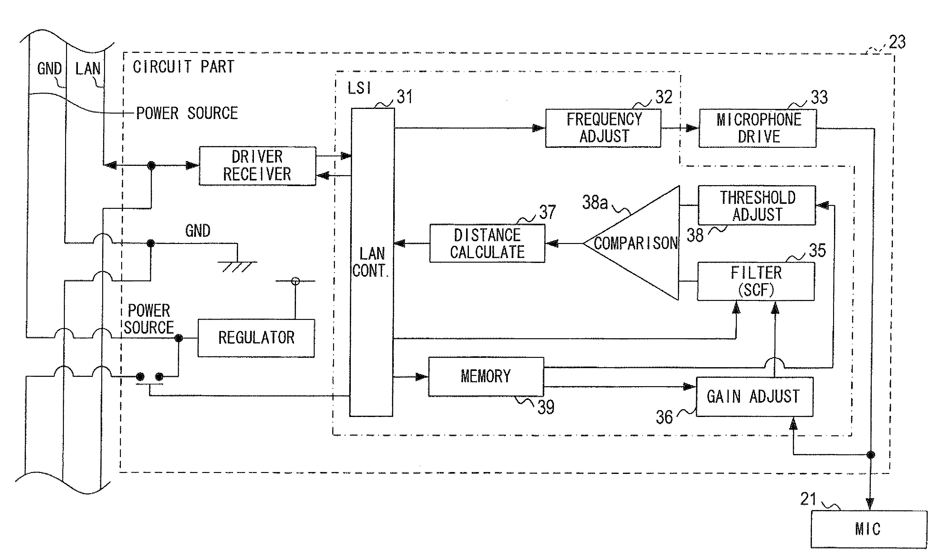
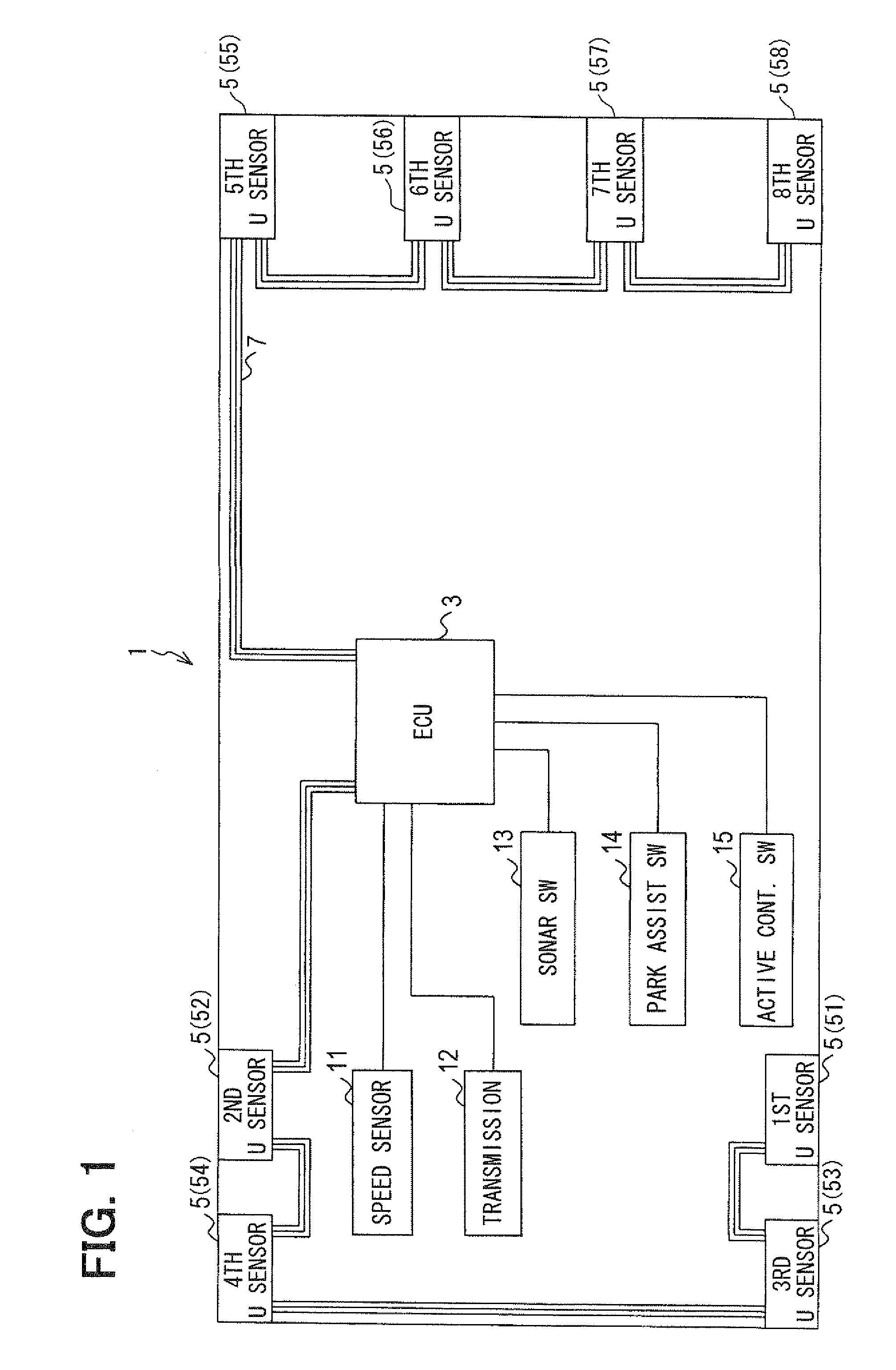
[0035]An obstacle detection apparatus 1 according to a first embodiment is described below with reference to the accompanying drawings. FIG. 1 is a block diagram illustrating a configuration of an obstacle detection apparatus 1. The obstacle detection apparatus 1 includes an electronic control unit (ECU) 3 as a controller, multiple ultrasonic sensors 5, and a serial communication line 7. The multiple ultrasonic sensor 5 includes a first ultrasonic sensor 5 (51), a second ultrasonic sensor 5 (52), a third ultrasonic sensor 5 (53), a fourth ultrasonic sensor 5 (54), a fifth ultrasonic sensor 5 (55), a sixth ultrasonic sensor 5 (56), a seventh ultrasonic sensor 5 (57), and an eighth sonic sensor 5 (58). The obstacle detection apparatus 1 further includes a speed sensor 11, a transmission device 12, a clearance sonar activation switch 13, a parking assist system activation switch 14, and an active control setting switch 15, signals from which are input to the ECU 3 directly. Alternative...

second embodiment

[0101]An obstacle detection apparatus 1 according to a second embodiment is described below.

[0102]In the second embodiment, the directivity and the sensing distance of the ultrasonic sensors 5 are changed based on a distance to an obstacle detected with the ultrasonic sensors 5. More specifically, in switching the operational mode of the ultrasonic sensor 5, the obstacle detection apparatus 1 according to the present embodiment performs procedure S140 corresponding to the below-described processes associated with FIG. 9. It should be noted that the apparatus 1 according to the first embodiment performs procedure S140 corresponding to the above-described processes S405 to S435 associated with FIG. 8.

[0103]According to the present embodiment, as shown in FIG. 9, the ECU 3 determines at S505 whether a change is made in an active control setting. When it is determined that no change is made in the active control setting, corresponding to “NO” at S505, the ECU 3 determines at S510 whethe...

third embodiment

[0118]Explanation on a third embodiment is described below.

[0119]According to the third embodiment, the above-described obstacle detection apparatus 1 is built into a parking assistance system. When this parking assistance system is activated, the parking assistance system searches for a parking space existing sideward of the vehicle (e.g., refer to A5 in FIG. 10A) while the vehicle is moving forwards, as shown in FIG. 10A. Then, when a user performs an operation for commanding the vehicle to enter a parking space, the vehicle enters a parking space while moving backward, as shown in FIG. 10B.

[0120]According to the parking assistance system that operates in the above manners, when the vehicle moves forwards, it is necessary to recognize a parked vehicle located relatively distant from the vehicle, and it is necessary to search for a parking space. In the above case, therefore, it is preferable that the search is made in the above-described long distance mode to restrict error detect...


PUM


Abstract

An obstacle detection apparatus for a vehicle is provided. The apparatus includes an ultrasonic sensor and a controller. The ultrasonic sensor detects a presence of an obstacle around the vehicle and a distance to the obstacle by transmitting an ultrasonic wave and receiving the ultrasonic wave reflected by the obstacle. The controller controls the ultrasonic sensor. The ultrasonic sensor includes an ultrasonic wave element. The ultrasonic wave element has multiple resonance modes. The ultrasonic sensor changes a directivity of the ultrasonic sensor by selecting one of the multiple resonance modes of the ultrasonic wave element in accordance with a command signal output from the controller.

Description

CROSS REFERENCE TO RELATED APPLICATION[0001]The present application is based on Japanese Patent Application No. 2007-177485 filed on Jul. 5, 2007, the disclosure of which is incorporated herein by reference.BACKGROUND OF THE INVENTION[0002]1. Field of the Invention[0003]The present invention relates to an obstacle detection apparatus.[0004]2. Description of Related Art[0005]An obstacle detection apparatus for a vehicle has already been put to practical use. Such an obstacle detection apparatus detects a presence of an obstacle around a vehicle and a distance to the obstacle. This type of obstacle detection apparatus is utilized in, for example, a system (e.g., a clearance sonar system) that warns a driver of a vehicle about risk of probable collision between the obstacle and the vehicle. Also, this type of obstacle detection apparatus is utilized in a system (i.e., a parking assist system) that searches for a parking area for parking a vehicle therein, and guides a vehicle to enter ...

Claims


Application Information

Patent Timeline
Patent Type & Authority Applications(United States)
IPC IPC(8): B60Q1/00G01S15/931
CPCG01S15/931G01S2015/936G01S2015/938G01S7/003
Inventor MAGANE, FUMIMASAKANI, HIROYUKITANAKA, SYOTAROU
Owner DENSO CORP
Why Eureka
Try Eureka