RFID integrated circuit with integrated antenna structure

a technology of integrated circuits and antenna structures, applied in the field of wireless communication, can solve the problems of antenna gain restriction, modulation techniques, power restrictions, etc., and achieve the effect of reducing the cost of antenna installation, and reducing the cost of installation

Active Publication Date: 2009-01-08
NXP USA INC
View PDF9 Cites 122 Cited by
  • Summary
  • Abstract
  • Description
  • Claims
  • Application Information

AI Technical Summary

Problems solved by technology

While the ISM frequency spectrum is unlicensed there are restrictions on power, modulation techniques, and antenna gain.
An issue with such three-dimensional antennas is that they cannot be implemented in the substantially two-dimensional space of an integrated circuit (IC) and/or on the printed circuit board (PCB) supporting the IC.
As such, due to the antenna size, it cannot be

Method used


Image

  • RFID integrated circuit with integrated antenna structure
  • RFID integrated circuit with integrated antenna structure
  • RFID integrated circuit with integrated antenna structure

Examples


Embodiment Construction

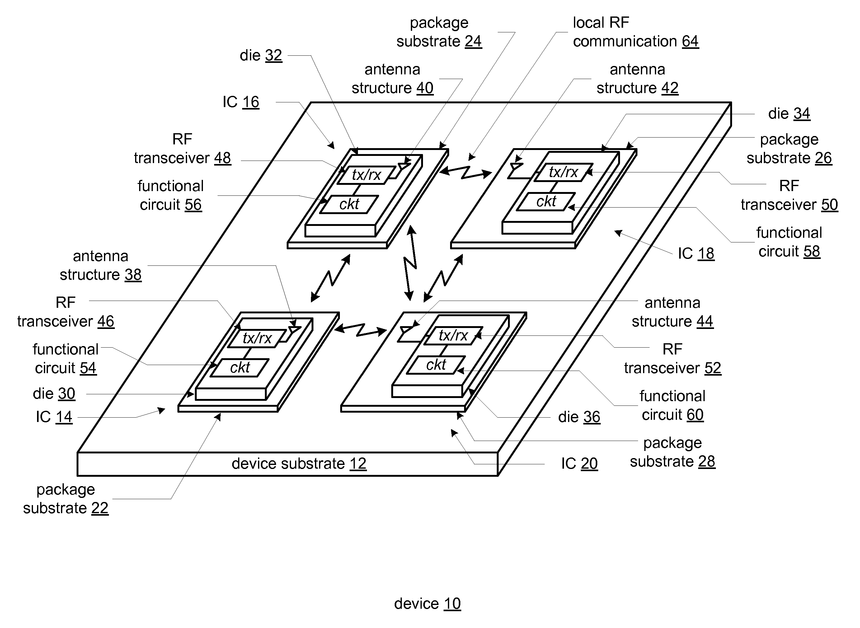
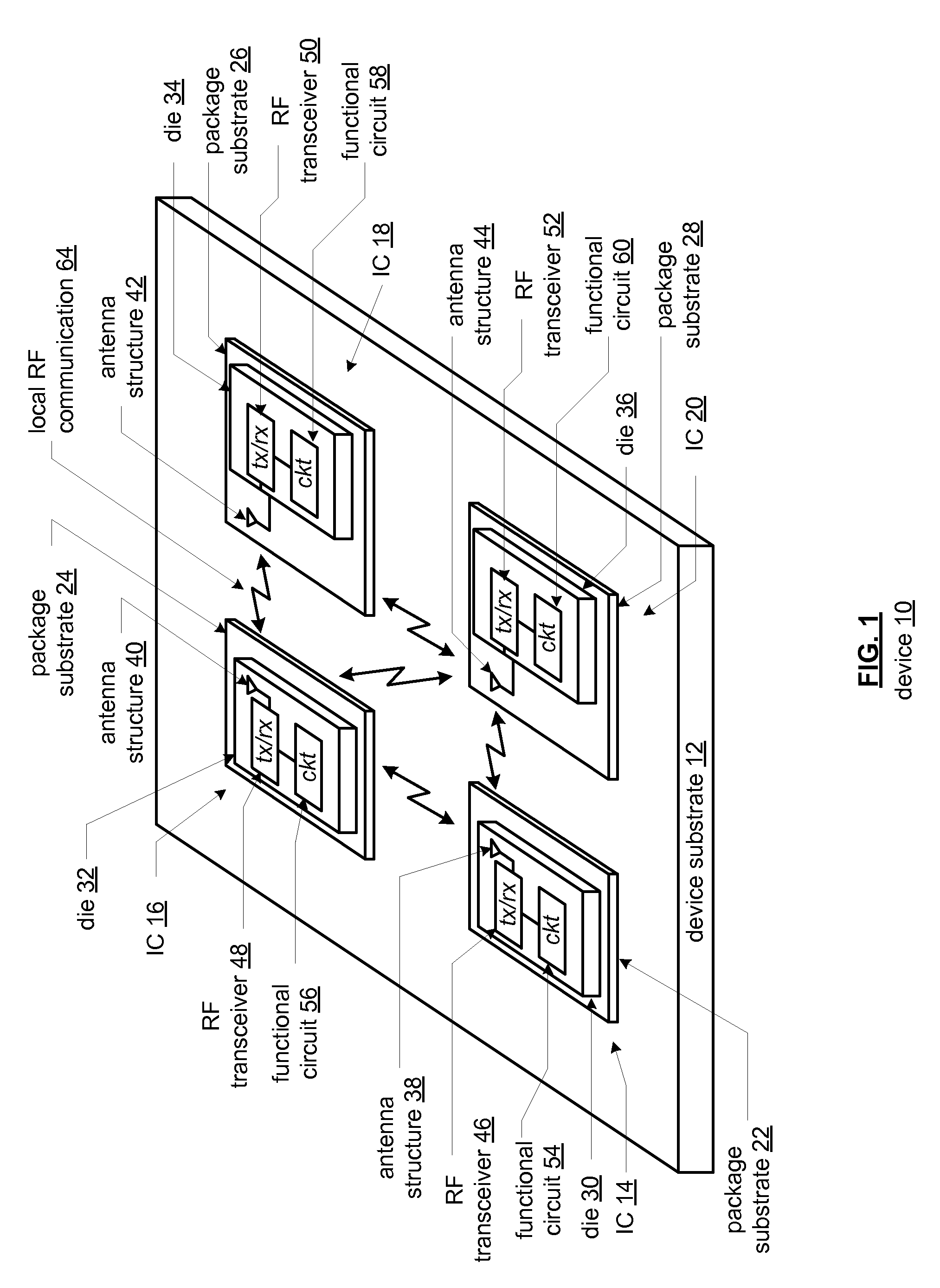
[0063]FIG. 1 is a diagram of an embodiment of a device 10 that includes a device substrate 12 and a plurality of integrated circuits (IC) 14-20. Each of the ICs 14-20 includes a package substrate 22-28 and a die 30-36. Dies 30 and 32 of ICs 14 and 16 include an antenna structure 38, 40, a radio frequency (RF) transceiver 46, 48, and a functional circuit 54, 56. Dies 34 and 36 of ICs 18 and 20 include an RF transceiver 50, 52 and a function circuit 58, 60. Package substrates 26 and 28 of ICs 18 and 20 include an antenna structure 42, 44 coupled to the RF transceiver 50, 52.

[0064]The device 10 may be any type of electronic equipment that includes integrated circuits. For example, but far from an exhaustive list, the device 10 may be a personal computer, a laptop computer, a hand held computer, a wireless local area network (WLAN) access point, a WLAN station, a cellular telephone, an audio entertainment device, a video entertainment device, a video game control and / or console, a radio...


PUM


Abstract

An integrated circuit for use in an RFID tag includes an integrated circuit die having a circuit, a radio frequency identification (RFID) interface for providing communication between the circuit and a remote RFID reader via RF signaling between the RFID interface and the remote RFID reader, and an antenna section for facilitating the RF signaling between the RFID and the remote RFID reader. A substrate is coupled to support the first integrated circuit die.

Description

CROSS REFERENCE TO RELATED PATENTS[0001]The present application claims priority under 35 U.S.C. 120 as a continuation-in-part of the U.S. patent application entitled, “AN INTEGRATED CIRCUIT ANTENNA STRUCTURE,” having Ser. No. 11 / 648,826, filed on Dec. 29, 2006 and as a continuation-in-part of the U.S. patent application entitled, “INTEGRATED CIRCUIT ASSEMBLY INCLUDING RFID AND COMPONENTS THEREOF,” having Ser. No. 11 / 472,205, filed on Jun. 21, 2006.[0002]The present application is further related to the following U.S. patent applications that are commonly owned, the contents of which are hereby incorporated by reference thereto:[0003]INTEGRATED CIRCUIT WITH POWER SUPPLY LINE ANTENNA STRUCTURE AND METHODS FOR USE THEREWITH, having Ser. No. ______, filed on ______;[0004]INTEGRATED CIRCUIT WITH BONDING WIRE ANTENNA STRUCTURE AND METHODS FOR USE THEREWITH, having Ser. No. ______, filed on ______;[0005]INTEGRATED CIRCUIT WITH ELECTROMAGNETIC INTRACHIP COMMUNICATION AND METHODS FOR USE THE...

Claims


Application Information

Patent Timeline
IPC IPC(8): G08B13/14
CPCG06K7/10237H01L2224/05554G06K19/07786H01L23/66H01L24/06H01L24/49H01L25/0655H01L25/16H01L2223/6677H01L2224/48091H01L2224/49175H01L2924/01005H01L2924/01014H01L2924/01015H01L2924/01027H01L2924/01031H01L2924/01061H01L2924/01083H01L2924/13091H01L2924/14H01L2924/1433H01L2924/19041H01L2924/19042H01L2924/19043H01L2924/19104H01L2924/30105H01L2924/30107H01L2924/3011H01Q1/2225H01Q1/2283H01Q1/38H01Q9/065H01Q23/00G06K19/07749H01L2224/48227H01L24/48H01L2924/01006H01L2924/01023H01L2924/01033H01L2924/01032H01L2924/0106H01L2924/1903H01L2223/6627H01L2924/00014H01L2924/30111H01L2224/023H01L2924/00H01L2224/45099H01L2224/05599H01L2924/0001
Inventor ROFOUGARAN AHMADREZA (REZA)
Owner NXP USA INC
Why Eureka
Try Eureka