Utility outlets having dynamically changing emergency evacuation routing

a technology of emergency evacuation and utility outlets, applied in the field of utility outlets, can solve the problems of insufficient procedures, the most dangerous route of the possible routes,

Inactive Publication Date: 2009-01-08
OPTIMAL INNOVATIONS INC
View PDF6 Cites 32 Cited by
  • Summary
  • Abstract
  • Description
  • Claims
  • Application Information

AI Technical Summary

Benefits of technology

[0007]The present invention is directed to devices, systems and methods that are capable of dynamically indicating the safest emergency evacuation routing based on conditions occurring at the time of the emergency. Specifically, the system uses utility outlets, such as electrical sockets and light switches, to indicate (via visual or audible indicators) the safest evacuation route based on conditions existing during an emergency. The use of utility outlets for the evacuation routes takes advantage of devices that must be installed in virtually all buildings at predictable locations. In one embodiment, a signal is sent from a sensor to one or more wall mounted light switches or power outlets causing the switch or outlet to display, perhaps in conjunction with other light switches and / or outlets, the direction to the appropriate exit.
[0008]In another embodiment, the switches and outlets are coordinated to act in a systemic approach that allows each light switch and / or power outlet to flash (possibly with direction indicators to the closest viable exit) and / or wail faster and faster to indicate its proximity to a viable and appropriate exit.

Problems solved by technology

While the procedure of posting or publishing evacuation routes may enhance safety in an emergency, there are certain situations in which these procedures are inadequate.
Significantly, the previously determined preferred route may be the most dangerous of the possible routes in a particular emergency.
In other words, a preferred route may become the most dangerous route based on the location of the cause of the emergency.
Accordingly, in a scenario where there are optional routes, the existing systems do not provide a means of indicating the safest routes based on the circumstances at the time of the emergency.
Further, smoke alarms, although very useful for determining the existence of fire, are typically poor at determining the room or location of the fire.
They do not detect heat / fire directly, and because smoke particles travel much quicker than fire or heat, smoke detectors are very poor at discriminating where a fire actually is.
In environments such as the home, it is not practical to post evacuation routes.
Even if such routes were to be posted, some occupants, such as young children, might not be able to read or remember the route.
Further, once the emergency condition exists it is usually too late (or too smoky) for anyone to stop and read the posted route information.
Compounding the problem even further is the fact that when smoke or chemicals reduce visibility, occupants of the premises, whether it be a room in a home, a room in a public facility or an office or hallway in a work environment, can become confused as to the nearest exit and thus be trapped, or waste precious time trying to escape the problem area.

Method used


Image

  • Utility outlets having dynamically changing emergency evacuation routing
  • Utility outlets having dynamically changing emergency evacuation routing
  • Utility outlets having dynamically changing emergency evacuation routing

Examples


Embodiment Construction

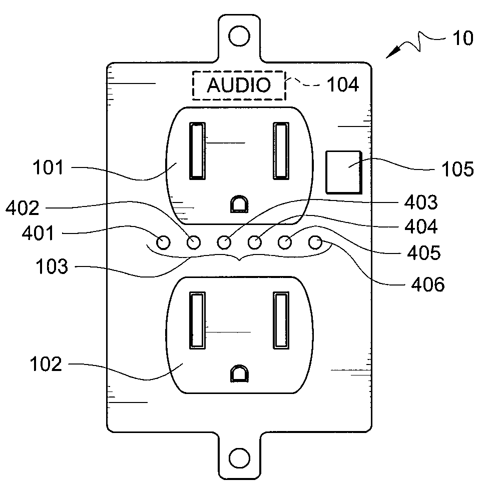
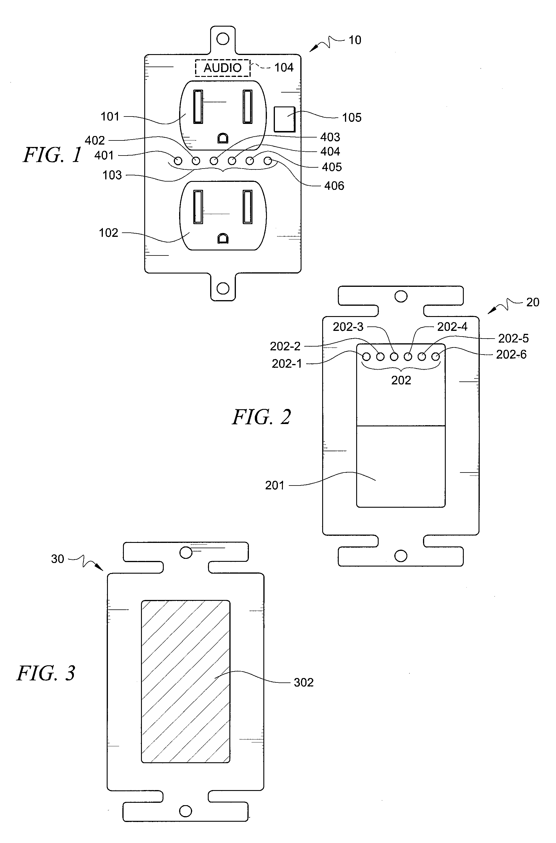
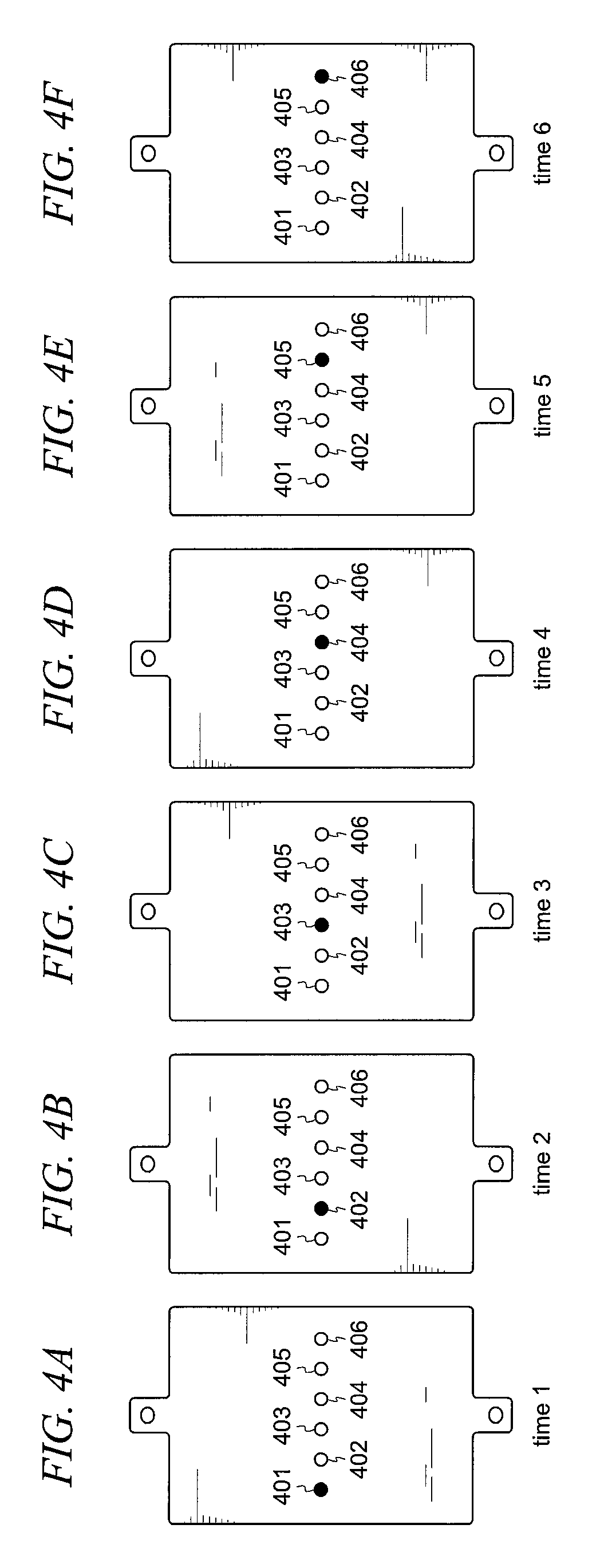
[0018]FIG. 1 is a diagram of one embodiment of the current invention showing a utility outlet. In this embodiment, utility outlet 10 has the primary purpose of providing a connection to a power source. Plugs are inserted into sockets 101 or 102 in the conventional manner so as to allow power to flow from the socket through the plug to the device being powered. In addition to serving as connection to a power source, utility outlet 10 serves as a device to indicate an evacuation route in the event it receives a signal that there is an emergency condition. The emergency signal may be received either via a power cable, a separate communication cable, wirelessly or from a device within the socket itself. When the emergency signal is received, the utility outlet displays the evacuation route by illuminating some light signal such as, for example, apparatus 103. Illumination apparatus 103 can be a single light source or it may comprise several individual light sources, such as illumination...


PUM


Abstract

Devices, systems and methods that are capable of dynamically indicating emergency evacuation routes in a premises. In the premises, utility outlets such as electrical sockets and light switches are used to indicate, visually and / or audibly, an evacuation route. The use of utility outlets to indicate the evacuation routes takes advantage of devices that must be installed in virtually all buildings at predictable locations.

Description

CROSS-REFERENCE TO RELATED APPLICATIONS[0001]The present application is related to co-pending, and commonly assigned U.S. patent application Ser. No. 11 / 683,304, Attorney Docket No. 66816 / P012US / 10609934, entitled “SYSTEMS AND METHODS FOR LINKING UTILITY CONTROL DEVICES;” U.S. patent application Ser. No. 11 / 683,327, Attorney Docket No. 66816 / P013US / 10609935, entitled “SYSTEM AND METHOD FOR INFRASTRUCTURE REPORTING;” U.S. patent application Ser. No. 11 / 683,298, Attorney Docket No. 66816 / P014US / 10614006, entitled “LIGHT SWITCH USED AS A COMMUNICATION DEVICE;” U.S. patent application Ser. No. 11 / 683,308, Attorney Docket No. 66816 / P015US / 10614005, entitled “SYSTEM AND METHOD FOR PREMISES MONITORING USING WEIGHT DETECTION;” U.S. patent application Ser. No. 11 / 683,326, Attorney Docket No. 66816 / P016US / 10614296, entitled “ANTICIPATORY UTILITY CONTROL DEVICE;” U.S. patent application Ser. No. 11 / 683,335, Attorney Docket No. 66816 / P017US / 10614295, entitled “PLUG AND PLAY UTILITY CONTROL MODU...

Claims


Application Information

Patent Timeline
Patent Type & Authority Applications(United States)
IPC IPC(8): G08B5/00
CPCG08B7/066G08B5/36H02G3/00
Inventor SCHOETTLE, ROLAND
Owner OPTIMAL INNOVATIONS INC
Why Eureka
Try Eureka