Electric Connector

a technology of electrical connectors and connectors, applied in the direction of coupling contact members, coupling device connections, material of connection contact members, etc., can solve problems such as miniaturization of spaces

Inactive Publication Date: 2009-01-08
FRAMATOME CONNECTORS INT SA
View PDF10 Cites 21 Cited by
  • Summary
  • Abstract
  • Description
  • Claims
  • Application Information

AI Technical Summary

Problems solved by technology

However, along with the further increase in the volume of information, the reality is that speeding up of signal transfer speed and an increase in the number of signal wires is being sought for information communication henceforwa

Method used


Image

  • Electric Connector
  • Electric Connector
  • Electric Connector

Examples


Embodiment Construction

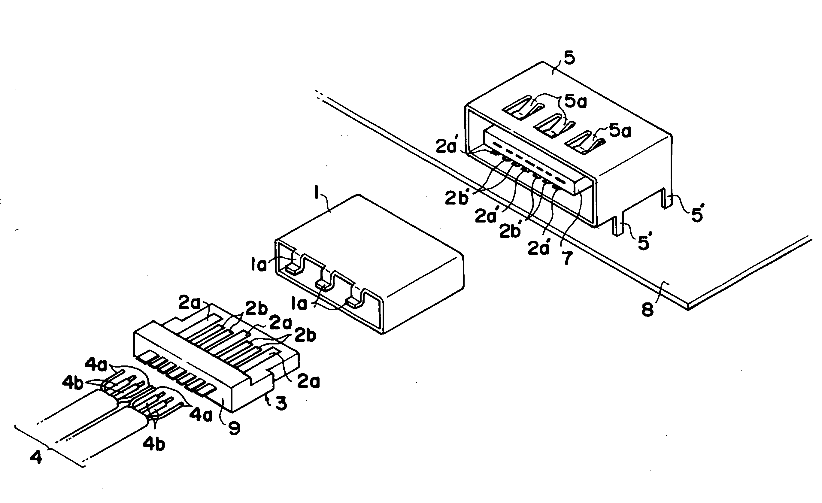
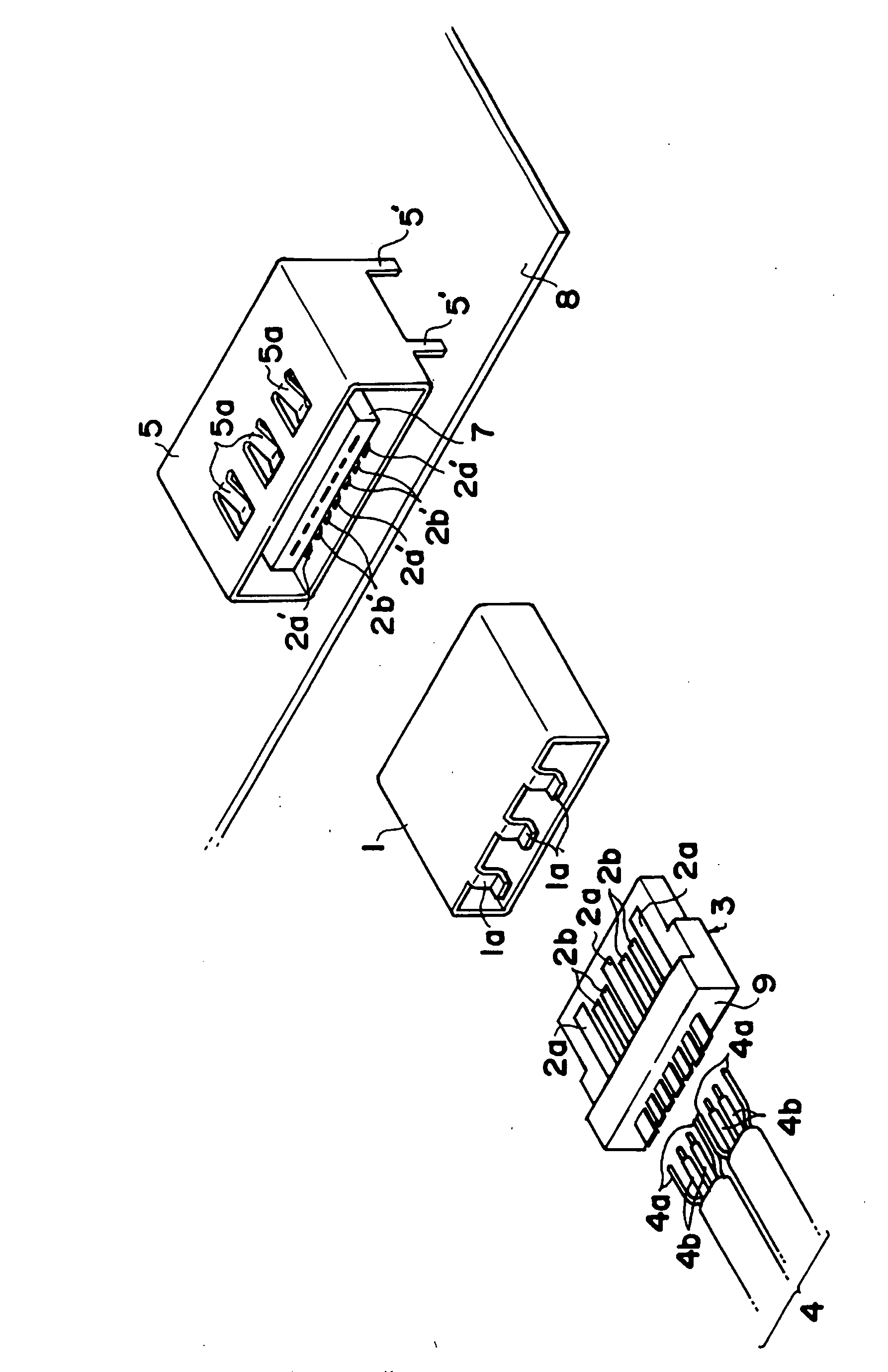
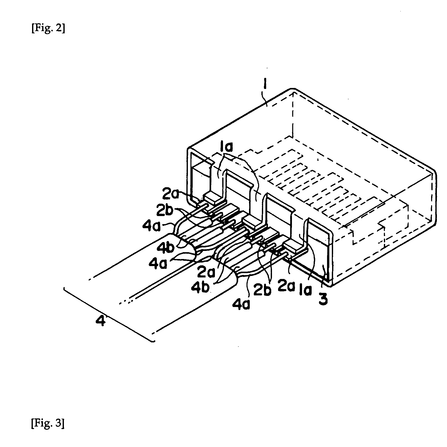
[0041]FIG. 1 is a block diagram showing the differential transmission cable-side connector and the printed circuit board-side connector of the present invention. FIG. 2 is a wiring diagram and an assembly diagram of the cable-side connector. FIG. 3 is an exploded view of the printed circuit board-side connector.

[0042]The cable-side connector according to the present invention shall be explained with reference to FIGS. 1 and 2. Said cable-side connector has a structure such that it electrically connects with two parallel differential transmission cables 4, and said differential transmission cable 4 internally comprises one pair of signal wires 4b and one pair of drain wires 4a. Additionally, said connector comprises the abovedescribed differential transmission cable 4, two pairs of signal contacts 2b, three ground contacts 2a, a carrier 3, and a first metallic shell 1.

[0043]Herebelow, each of the constituent elements shall be described.

[0044]The signal contacts 2b form neighboring pa...


PUM


Abstract

The deterioration of the signal characteristic of a differential transmission connector is improved. The connector connected electrically with a plurality of cables each including a pair of signal lines and a pair of drain lines includes a pair of adjacent signal contactors connected with the pair of signal lines of the cable, a ground contactor connected with at least one drain line of the cable, a carrier on which the pair of signal contactors and the ground contactor are alternately arranged on the same plane in a line in the width direction perpendicular to the axial direction of the cable, and a first metal shell covering at least a part of the ground contactor, a part of the signal contactors and a part of the carrier. The connector is characterized in that the first metal shell has at least one ground contactor and a first contact.

Description

TECHNICAL FIELD[0001]The present invention concerns a connector capable of electrically connecting differential transmission cables, and pertains to a connector that provides an excellent high speed signal characteristic.BACKGROUND ART[0002]In recent years, along with the increase in information volume, and the increase in information transmission speed, a data transfer standard called “serial ATA” has been the mainstream interface between devices that are accessories to personal computers and the like. A serial transmission method refers to a method where information is transmitted 1 bit at a time using one transmission path, and since the number of signal wires is low, interference between signal wires does not readily occur, so such a method has the characteristic of being advantageous for increasing speed. Additionally, from the standpoint of signal voltage, it is advantageous because the voltage can be set low, around plus or minus 250 mV, and further, resistance to external no...

Claims


Application Information

Patent Timeline
IPC IPC(8): H01R13/648
CPCH01R9/034H01R13/26H01R12/707H01R23/6873H01R13/65802H01R12/716H01R12/724H01R13/6582H01R13/6594H01R13/65914H01R24/20
Inventor YAMAZAKI, HARUKI
Owner FRAMATOME CONNECTORS INT SA
Why Eureka
Try Eureka